R8C/20 Group, R8C/21 Group 12. Interrupts
Rev.2.00 Aug 27, 2008 Page 96 of 458
REJ09B0250-0200
12.1.6.4 Interrupt Sequence
An interrupt sequence is performed between an interrupt request acknowledgement and interrupt routine
execution.
When an interrupt request is generated while an instruction is executed, the CPU determines its interrupt
priority level after the instruction is completed. The CPU starts the interrupt sequence from the following
cycle. However, in regards to the SMOVB, SMOVF, SSTR or RMPA instruction, if an interrupt request is
generated while executing the instruction, the MCU suspends the instruction to start the interrupt sequence.
The interrupt sequence is performed as follows.
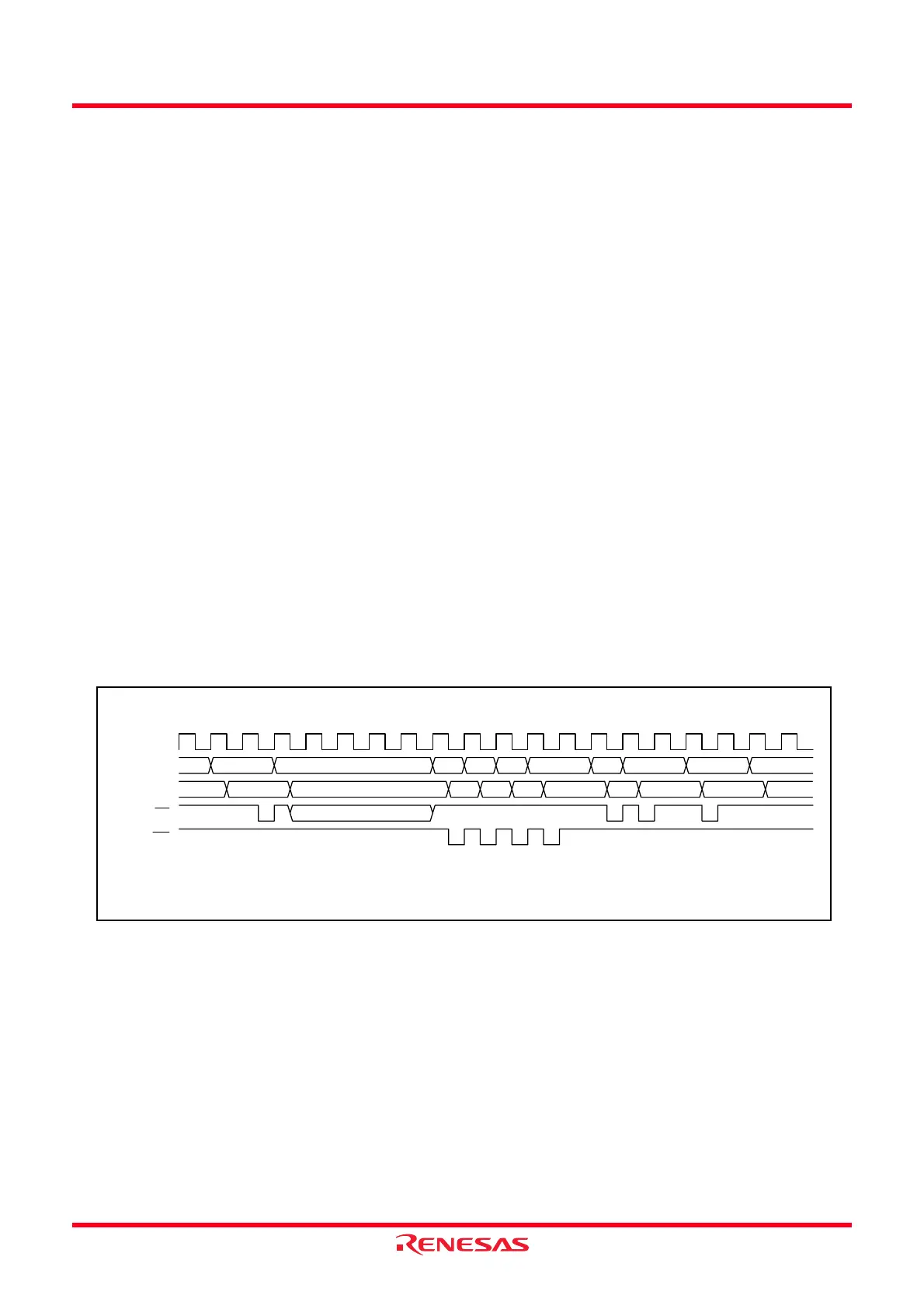
Figure 12.6 shows the Time Required for Executing Interrupt Sequence.
(1) The CPU gets interrupt information (interrupt number and interrupt request level) by reading the
address 00000h. The IR bit for the corresponding interrupt is set to 0 (interrupt not requested)
(2)
.
(2) The FLG register immediately before entering the interrupt sequence is saved to the CPU internal
temporary register
(1)
.
(3) The I, D and U flags in the FLG register are set as follows:
The I flag is set to 0 (disables interrupts).
The D flag is set to 0 (disables single-step interrupt).
The U flag is set to 0 (ISP selected).
However, the U flag does not change state if an INT instruction for software interrupt number 32 to 63
is executed.
(4) The CPU’s internal temporary register
(1)
is saved to the stack.
(5) The PC is saved to the stack.
(6) The interrupt priority level of the acknowledged interrupt is set in the IPL.
(7) The starting address of the interrupt routine set in the interrupt vector is stored in the PC.
After the interrupt sequence is completed, the instructions are
NOTES:
1. This register cannot be used by user.
Figure 12.6 Time Required for Executing Interrupt Sequence
2. For operations of the IR bit, refer to 12.5 Timer RD Interrupt, Clock Synchronous Serial I/O with
Chip Select Interrupts and I
2
C bus Interface Interrupts (Interrupts with Multiple Interrupt
Request Sources).
1234567891011 12 13 14 15 16 17 18 19 20
CPU clock
Address bus
Data bus
RD
WR
Address
0000h
Indeterminate
Indeterminate
Indeterminate
Interrupt
information
SP-2 SP-1 SP-4 SP-3 VEC VEC+1 VEC+2 PC
SP-2
contents
SP-1
contents
SP-4
contents
SP-3
contents
VEC
contents
VEC+1
contents
VEC+2
contents
NOTE:
1. The indeterminate state depends on the instruction queue buffer. A read cycle occurs when the instruction queue
buffer is ready to acknowledge instructions.
 Loading...