1. Start the SP mode.
2. Select SP 5902 1 and output the ‘Trimming Area’ pattern (pattern 10).
3. Make sure that the four corners of the pattern make right angles:
•
If they make right angles, you do not need to adjust the laser unit alignment.
• If they do not make right angles, go on to the next step.
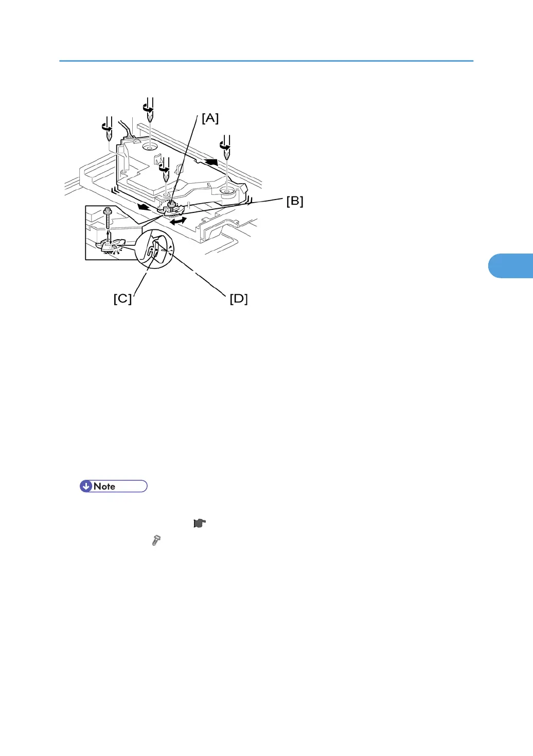
4. Check the screw position on the lever [B].
• If the screw is in the hole [C], go on to the next step.
• If the screw is in the slot [D], loosen the screw on the lever, loosen the four screws on the laser
unit, and go on to step 9.
• The initial position of the screw is in hole [C].
5. Four screws in the laser unit ( p.96)
6. Remove the lever
(
x 1), confirm the position of the hole beneath the slot [D], and reinstall the lever.
7. Install the screw
(through the slot [D]) loosely into the hole beneath the slot (do not tighten the screw).
8. Install the four screws for the laser unit loosely (do not tighten the screws).
9. When you rotate the lever clockwise or counterclockwise by one notch of the lever, the corners of the
pattern shift by ±0.4 mm (from the leading and trailing edges). See the trim pattern made in step 2,
and find how much the corners should be shifted.
Laser Unit
99
 Loading...