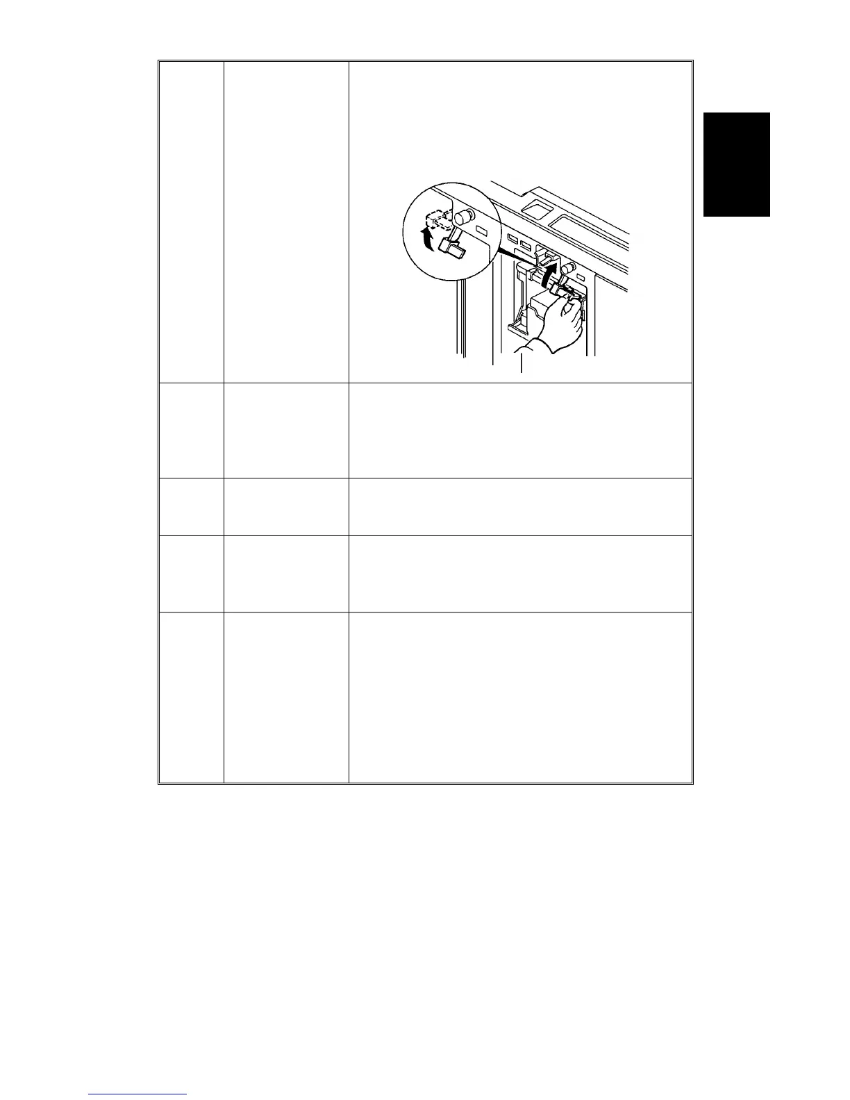
4. Drum Connector
To ensure drum connection, a drum lock lever is
added inside the front door. To remove the
drum from the machine, the drum release lever
must be pulled up to disconnect the drum
connector.
5.
Ink Detection
Board
The location of the ink detection board has been
changed from the upper side to the right side of
the drum shaft. The ink type switch (SW901),
which was not used (always set at oil type), has
been removed.
6. Drum Shaft
To supply ink to the ink roller evenly, the second
ink supply hole (count from the front side) of the
drum shaft is covered with a strip of tape.
7.
Exit Pawl Air
Pump
To ensure paper separation from the drum, the
exit pawl air pump system is standardized. (The
pump system can optionally be installed on the
VT2000 series.)
8.
Thermal Head
Drive
The thermal head drive board has been
removed. The function of the board has been
moved to the image processing board and the
main board.
The thermal head voltage is directly applied
from the power supply unit. The main board
applies signal to the PSU to supply thermal
head voltage only during the master making
process.
Overall
Information
C216 1-5 SM