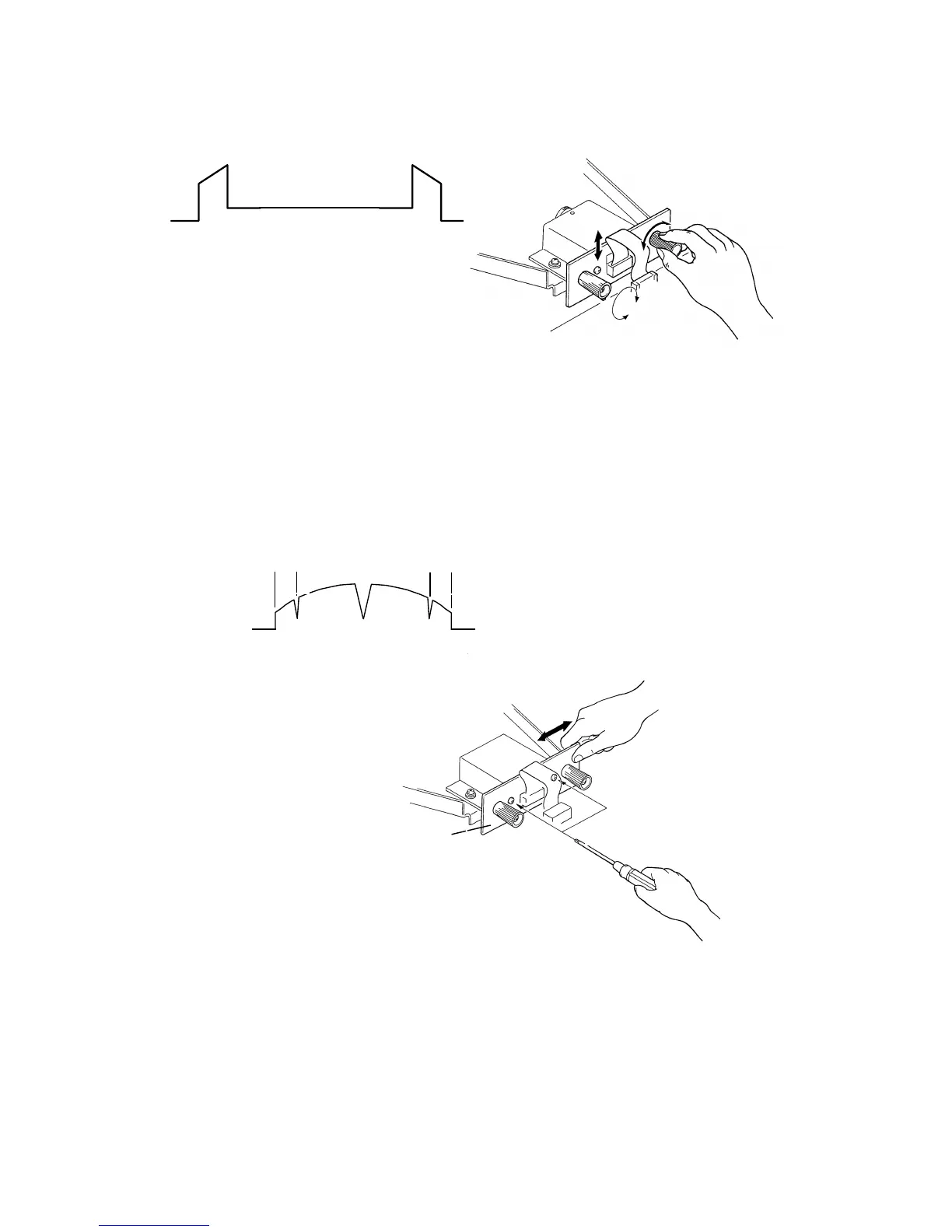
1.4 SCAN LINE POSITION ADJUSTMENT
Set the test chart R-21 so that the 1 mm black line is positioned 16 mm away
from the edge of the lower original guide plate.
Adjust the CCD board position so that the shape of the wave is similar to the
above illustration.
1.5 READING START POSITION ADJUSTMENT
(In The Main Scan Direction)
Set the test chart so that the center line, located at the leading edge of the
test chart, is positioned above the original leading edge sensor actuator.
Then feed the test chart so that the center line can be read.
Adjust the CCD board position so that the above wave is displayed.
[E]
[D]
L = L’
L
L’
C216 5-4 SM