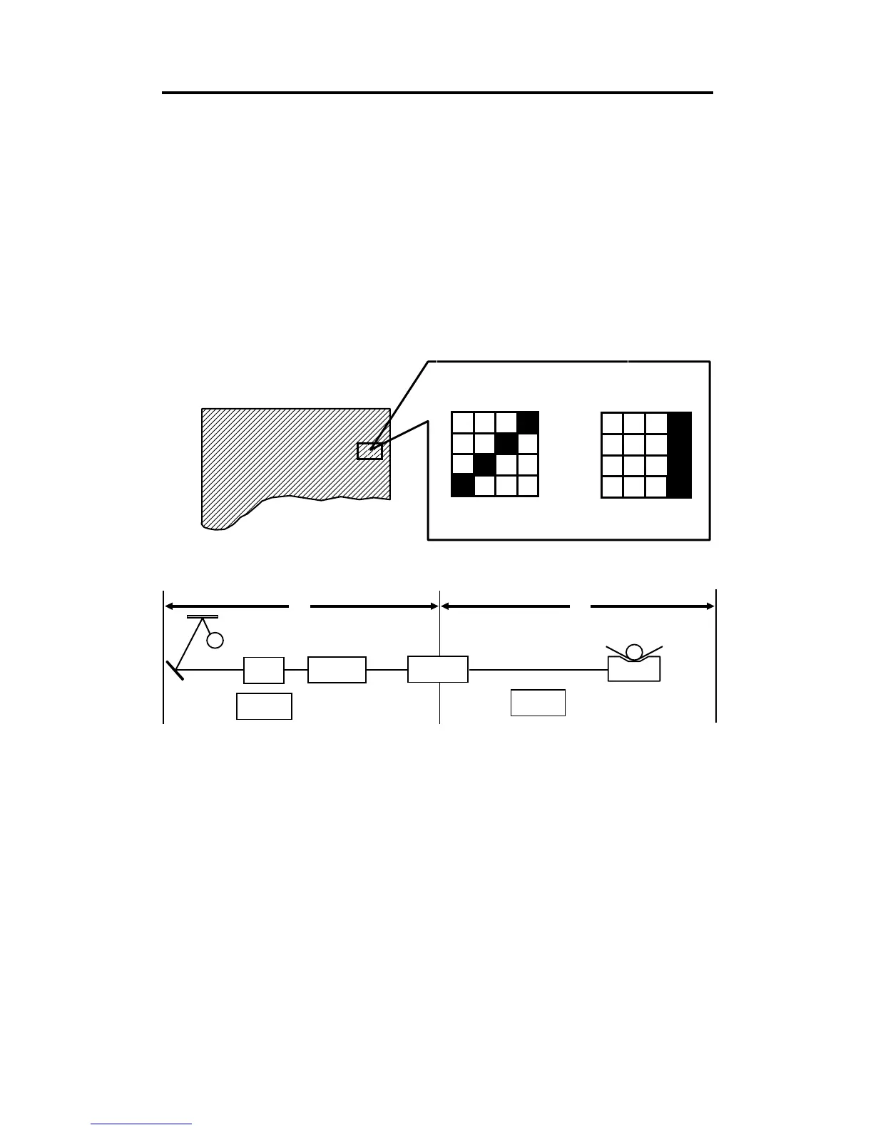
4. TEST PATTERN IMAGE MODE
The purpose of this mode is to distinguish whether the cause of the image
problem is located before or after image processing.
Output image: The normal output of this test pattern image mode is one
of the dither matrix pattern as illustrated below.
Master processing length:
Main scan (Horizontal) direction: Full width of the thermal head
Sub-scan (Vertical) direction: Same as the vertical size of
the original set on the original
table.
This test pattern is generated by the image processing PCB.
[Example] Problem: Vertical white lines appear on the print.
Possible Cause 1 If the same problem appears on the output
image from the thermal head in test pattern
image mode, the cause should be in area
B, as shown above.
Possible Cause 2 If the output image from the thermal head is
correct in test pattern mode but the output
image in the normal mode is incorrect, the
cause should be in area A, as shown
above.
Test Pattern Image
Test Pattern in
Line Mode
Test Pattern in
Photo Mode
Magnified Test Pattern Image
Image
Processing PCB
A/D Conversion
PCB
CCD
Original Feed
Motor
Master Feed
Motor
Thermal Head
B
A
Fluorescent Lamp
SM 4-8 C216