1. MAINTENANCE TABLE
The following VT2105 tables are identical to those from the VT2000 series.
• Lubrication Points
• User’s Maintenance
• Table of Periodic Inspection
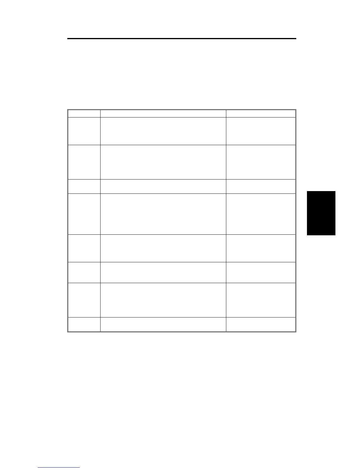
1.1 TABLE OF SERVICE CALL INDICATIONS
Indication Trouble Possible cuses
E 01
Malfunction in cutter section:
The cutter does not reach both right and left
cutter position switches within 2 seconds.
1) Drive wire cut
2) Drive section
malfunction
3) No power supply
E 02
Malfunction in the paper table drive section:
The lower limit sensor or the paper table height
sensor status does not change even though the
paper table UP or Down signal is applied.
1) Drive worm gear broken
2) Mounting screw of the
worm gear broken
3) No power supply
E 03 Malfunction in the program.
1) Defective PROM
2) Defective control PCB
E 04
Temperature of the thermal head or the power
supply unit is high:
Temperature of the thermal head becomes
greater than 57°C or the temperature of the
power supply unit becomes greater than 85°C
when the machine is in stand-by condition.
1) Defective thermistor
2) Defective thermal head
3) Defective power supply
unit
E 05 Malfunction in the image shifting section:
1) Encoder connector of
the image shifting
sectiond is connected.
2) Defective encoder
E 06
Mechanical lock:
Drum rotation sensor detects that the drum
rotation speed is abnormal.
1) Mechanical lock
2) Main motor failure
E 07
Malfunction in the program (PROM). When using
I/O check mode, "E 07" lights up if the ROM is
defective.
NOTE:
When "E 03" is lit, access I/O check
mode to check if the PROM is defective.
Defective ROM
E 08 Thermal head drive signal (ENL) is defective.
Defective image
processing board.
Service
Tables
C216 4-1 SM