12 WiNG-MGR User Guide 800.518.1519
1 System Overview
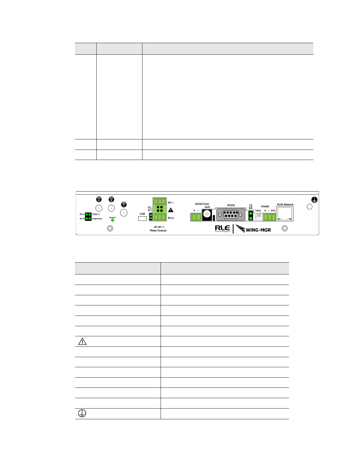
1.3. Physical Connections
Figure 1.1
WiNG-MGR Physical Connections
5 System
900MHz
WiNG-MGR
868MHz
WiNG-MGR
Indicates on which radio communications channel set the
manager is operating:
• Blue blink pattern - WiNG-MGR is operating on the primary
900MHz channel set.
• Green blink pattern - WiNG-MGR is operating on the
alternate 900MHz channel set.
• Purple blink pattern - WiNG-MGR is operating on the
primary 868MHz channel set.
• Yellow blink pattern - WiNG-MGR is operating on the
alternate 868MHz channel set.
6 RO1 | RO2 The relay output is activated
7 RS485 RX TX RS485 Receive/Transmit status LED
LED Label Description
Table 1.1
WiNG-MGR LED Indicators
Item Description
Antenna A RP-SMA connector
Antenna B RP-SMA connector
Antenna C RP-SMA connector
USB USB mini B connector
RO 1 Relay output 1 (NC/NO/C)
RO 2 Relay output 2 (NC/NO/C)
Caution! Potential high voltage connection
24 VDC/VAC Power terminal block
Jack Wall adapter connector
RS232 DB9 female connector port
RS485 Term 1 (unused); 2 100 ohm termination switch
RS485 Port RS485 circuit connector (+ - GND)
RJ45 Network 10/100 BASE-T connector Ethernet port
Earth ground connection
Table 1.2
WiNG-MGR Physical Connection Descriptions