72 WiNG-MGR User Guide 800.518.1519
4
4.2.3 Function 06: Preset Single Register & Function 16:
Preset Multiple Registers
To set the relay outputs over Modbus, first set the relay activation mode must be set to Modbus
only. Do this in the web interface, at the bottom of the Digital IO Configuration page - Chapter
3, “Relay Outputs” on page 44. The master must then send a Preset Single or Preset Multiple
Register request packet.
4.3. RTU Framing
The example below shows a typical Query/Response from a WiNG-MGR.
Slave address 2 responds to Function Code 4 with six bytes of hexadecimal data and ends with
CRC16 checksum.
Register Values:
40001 = 0000 (hex)
40002 = 0000 (hex)
40003 = 0001 (hex)
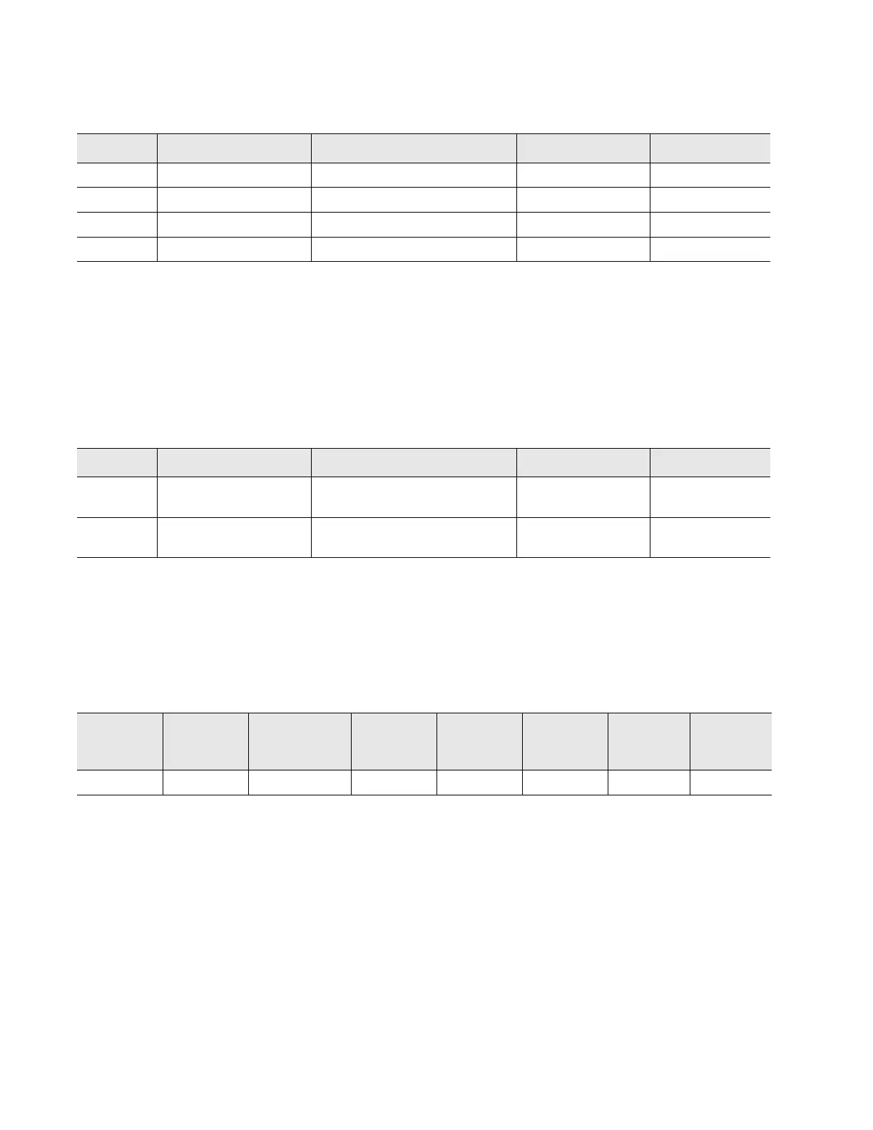
Register Name Description Units Range
30001 Digital Input 1 Digital Input 1: 1=0, 0=off uint16 0-1
30002 Digital Input 2 Digital Input 2: 1=0, 0=off uint16 0-1
30003 Digital Input 3 Digital Input 3: 1=0, 0=off uint16 0-1
30004 Digital Input 4 Digital Input 4: 1=0, 0=off uint16 0-1
Table 4.5
Read Input Registers
Register Name Description Units Range
49001 Relay K1 Relay 1 Activation: 1=active,
0=inactive
uint16 0-1
49002 Relay K2 Relay 2 Activation: 1=active,
0=inactive
uint16 0-1
Table 4.6
Preset Single and Multiple Registers
Slave
Address
Function
Code
Count Bytes
of Data
Register
Data
Msb Lsb
Register
Data
Msb Lsb
Register
Data
Msb Lsb
CRC 16
“Lsb”
CRC 16
“Msb”
02 04 06 00 00 00 00 00 01 B5 A3
Table 4.7
Response Sample