AX10 Palletizing Solution
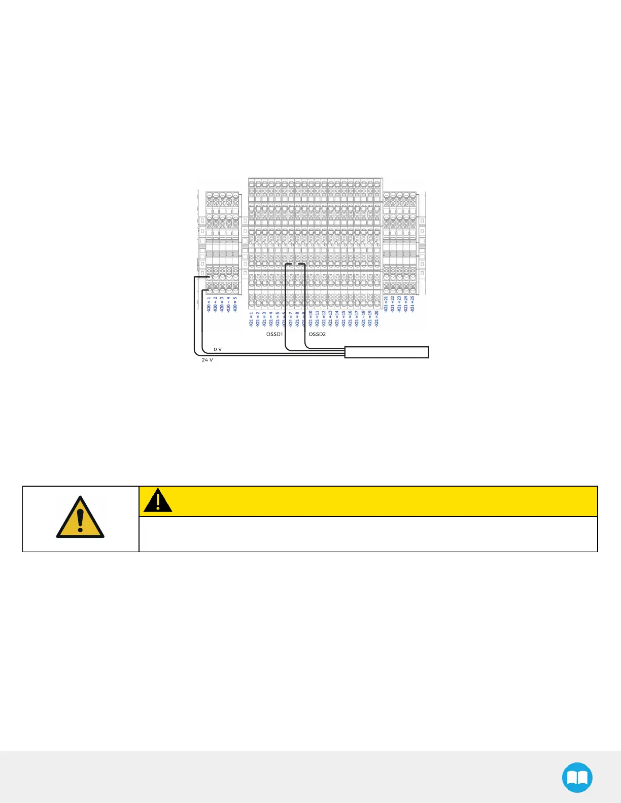
4. Remove the first jumper (-X21.7.1 to -X21.7.3).
5. Connect the end of the first OSSDwire (OSSD1) to -X21.7.3.
6. Remove the second jumper (-X21.8.2 to -X21.8.3).
7. Connect the end of the second OSSDwire (OSSD2) to -X21.8.3.
8. Connect the 24 V wire to an empty connection on terminal bank -X20, level 2 (e.g., -X20.1.2).
9. Connect the 0 V wire to an empty connection on terminal bank -X20, level 1 (e.g., -X20.1.1). The result should like the figure
below.
Fig. 6-7: Example of OSSD Signals Connections
10. Close the linear axis controller.
6.3.2. 24 V Safety Devices (Dry Contact)
Follow the instructions below to integrate safeguard devices using 24 V power supply (e.g., : door switch, limit switch).
CAUTION
Shut down the robot and power off the linear axis controller before making inter-controller and
safety signal connections.
1. Open the linear axis controller.
2. Run the safety device cable inside via the cable gland under the controller.