Robotiq Screwdriving Solution - Instruction Manual
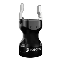
3.5.2.Robotiq Screwdriver
Installation on CB-SeriesUniversal Robots
Installation on CB-Seriesrobots requires the FT 300-SForce Torque Sensor and its corresponding hardware and tools.
Please refer to the Quickstart Guide of the FT 300-SForce Torque Sensor provided in the kit.
Otherwise, you can also refer to the user manual of the FT 300-SForce Torque Sensor for further technical information.
Caution
Leave enough excess cable to allow full robot movement.
1. Route the High-flex cable to the robot controller using a cable management method that corresponds to the work envir-
onment and to the application at hand.
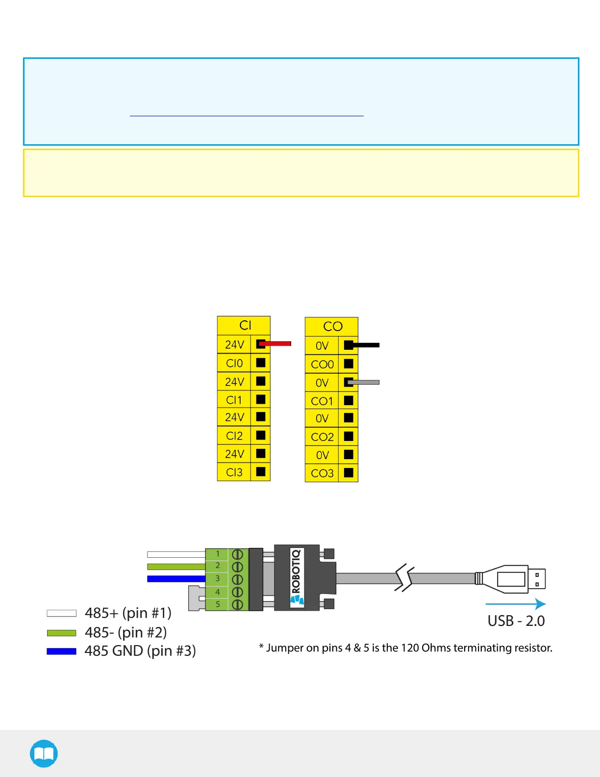
2. At the robot controller end of the High-flex cable, connect the red wire to a 24 VConfigurable Input in one of the robot con-
troller’s terminal blocks.
3. At the robot controller end of the High-flex cable, connect the black and gray wires to a 0 V Configurable Output in one of
the robot controller’s terminal blocks.
Fig. 3-2: Power Supply Wiring.
4. Connect the communication wires to the RS-485 to USB converter.
Fig. 3-3: Communication Wiring.
5. Connect the RS-485 to USB converter to a USB port of the robot controller.
25