Robotiq Screwdriving Solution - Instruction Manual
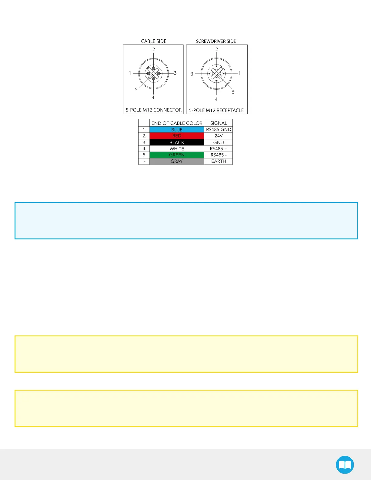
The figure below illustrates the Screwdriver’spigtail connector from the coupling (ACC-CPL-008), the device cable on the robot
side (CBL-COM-2065-10-HF) and their associated pinout.
Fig. 3-4: Pinout of the Screwdriver pigtail and device cable.
3.5.3.Robotiq Screw Feeder
Info
For the following steps, please refer to the Screw Feeder Nomenclature section for a detailed view of the back of the
device.
1. Connect the device end of the power supply cable to the power input at the back of the Screw Feeder.
2. Connect the other end of the power supply cable to a 100 V- 240 V electrical outlet.
3. Set the configuration toggle switch to PNP.
4. Connect the wires at the end of the I/O signalscable to available digital I/O terminal blocks in the robot controller:
l
Black wire (ground): 0 VDigital Output
l
Brown wire (status signal): Digital Input 0, 1, 2 or 3
l
Blue wire (ready signal): Digital Input 0, 1, 2 or 3 (different from brown wire)
Caution
Do not connect the wires in configurable I/O terminal blocks: the signalswill not be made available in the programming
interface.
5. Secure each connection using a 2.5 mm slotted screwdriver.
Caution
The assignment of Digital Input numbers to their corresponding signal wire should be duly noted asthey will be
required for configuring the communication between the Screw Feeder, the robot controller and the Screwdriver.
26