Robotiq Screwdriving Solution - Instruction Manual
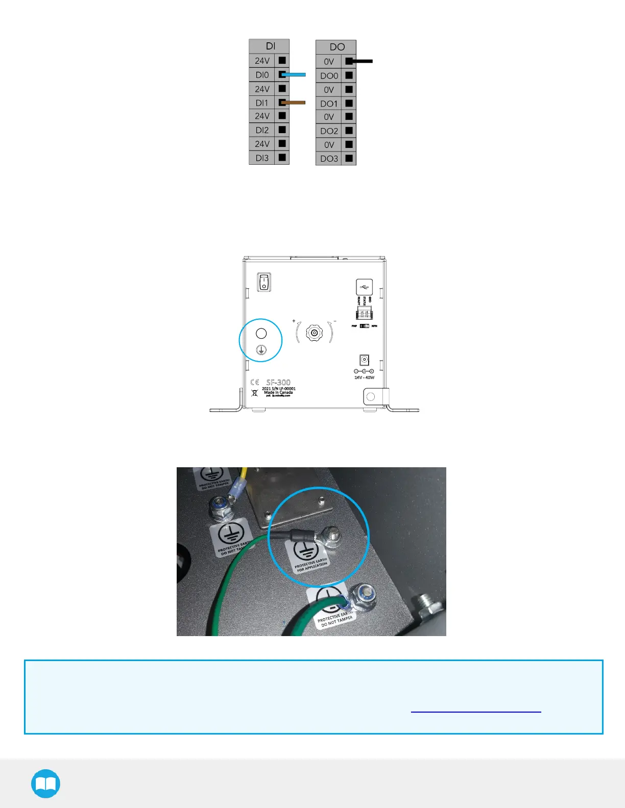
Fig. 3-5: Example of Digital Input/Output terminal assignment for the Screw Feeder.
6. Connect the protective earth cable (green)to the protective earth ring terminal at the back of the feeder on one end, and to
the screw connection marked with earth symbols (protective earth for application) inside the robot controller on the other
end. The nut for the screw connection on the robot side isincluded in the provided kit.
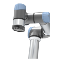
Fig. 3-6: Earth Screw Connection at the Back of the Screw Feeder.
Fig. 3-7: Screw Feeder Earth Screw Connection in Robot Controller.
Info
The USB type-B female connector at the back of the Screw Feeder and the provided USB cable should only be used in
case a firmware update isrequired. If such a situation occurs, please contact the Robotiq support department for
assistance.
27