GND
GND
+12V
INPUT
GND
GND
+12V
INPUT
Polarity= NO
GND
GND
+12V
INPUT
Polarity: NC
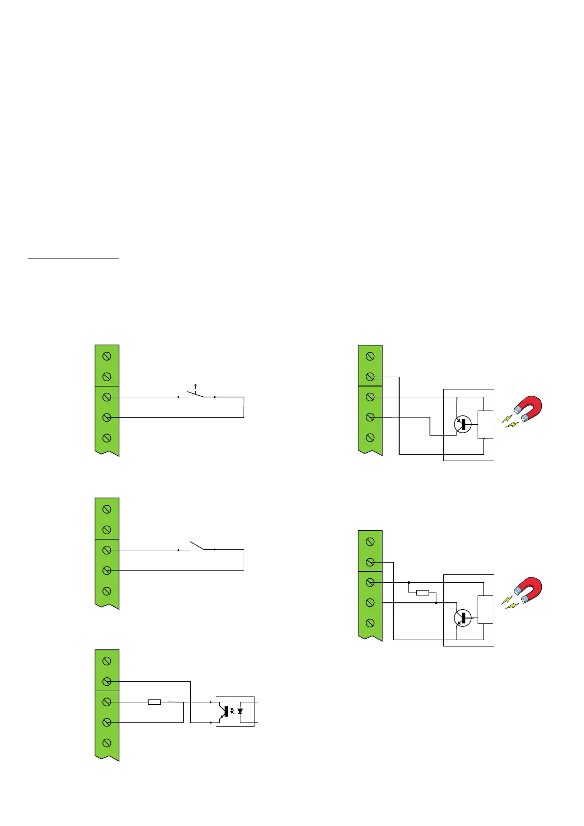
Optocoupler-Output (NPN) PULLUP-Resistor needed
10K
Mechanical NO contact
Mechanical NC contact
NPN NO: Polarity=NC
NPN NC: Polarity=NO
GND
GND
+12V
INPUT
PNP NOr: Polarity=NO
PNP NC: Polarity=NC
CONTROL
PNP
+
-
CONTROL
NPN
+
-
GND
GND
+12V
INPUT
10K
NPN NO: Polarity=NC
NPN NC: Polarity=NO
Inductive Sensor NPN-Output - PULLUP-Reistor needed
Inductive sensor with PNP output
34
Input 3: Z LIM
The input must be activated in the settings! Input for limit switch of the Z axis. You can use
potential-free contacts of a mechanical limit switch or inductive proximity switches (see below)
When the input is activated, the control switches to a safe state and ends running cycles until a
release has been given with the STOP key.
Input 3: X LIM
Like Z LIM, only for X axis
Input 4: ERROR
The input must be activated in the settings! input for an error signal, e.g. from the motor driv-
ers. All cycles are immediately interrupted in the event of a trip until the fault condition has
been rectied and a release with the STOP key has been given.
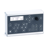
Wiring examples
In addition to the input connection, 12V is available, as are two GND terminals (GND) to ensure
the power supply of sensors.