35
The controller has 4 digital outputs which can be used for control purposes.
Output voltage: Identical with voltage at OUTPOW IN, maximum 24VMaximum output current:
500mA per outputAll outputs are short-circuit proof and equipped with free-wheeling diodes.
Resistive and inductive loads can be switched.
The output stages switch DC voltage which is applied to OUTPOW IN. You can bridge be-
tween +12V and OUTPOW IN, then 12V is switched to the outputs. If you want to use an
external voltage it can be connected to OUTPOW IN. Up to 24V can be switched in this
way.
Output 1: ESTOP FOLLOW
The output switches when an EMERGENCY STOP has been activated. It is possible to specify a
delay time in the settings, then this output switches delayed after the emergency stop to switch
o the power supply completely, for example after braking the drives.
Settings -> Outputs -> ESTOP FOLLOW Delay
See also EMERGENCY STOP
Output 2: SPINDLE STOP
This output is used to switch o the spindle. It is activated at the end of a cycle and after an
emergency stop. The output is activated immediately after the emergency stop has been trig-
gered and can thus stop the spindle in a controlled manner via a frequency converter. The
duration of the switching signal can be set in the settings:
Settings -> Outputs -> SPINDLE STOP Switch duration
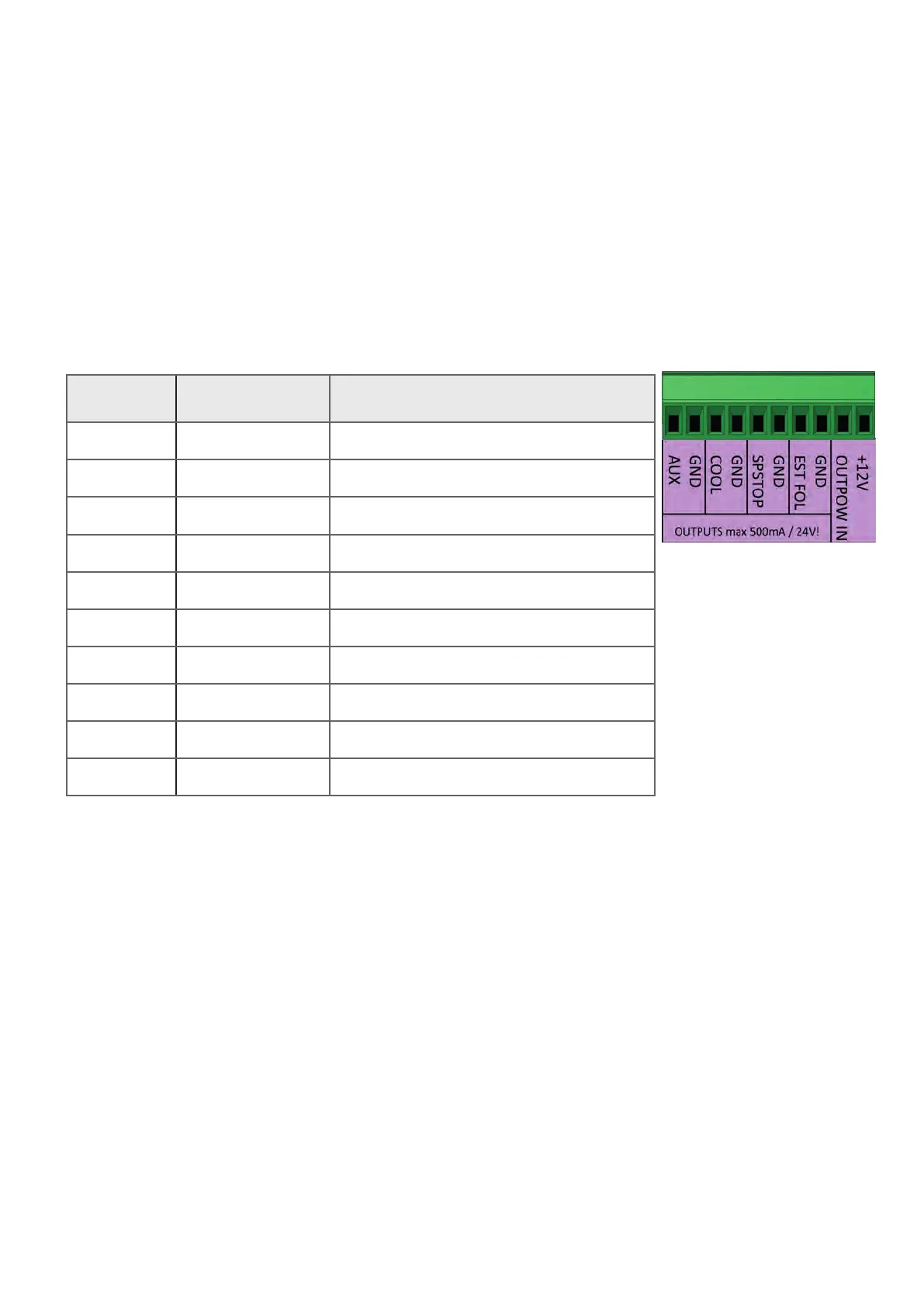
DIGITAL OUTPUTS
Name Function
1 4: AUX Output AUX
2 GND GND, 0V
3 3: COOL Cooling output
4 GND GND, 0V
5 2: SP STOP Spindle Stop
6 GND GND, 0V
7 1: ESTOP FOL ESTOP Follow
8 GND Masse, 0V
9 OUTPOW IN Power supply for outputs
10 +12V +12V