CAUTION
Observe the maximum voltage of 30V and the maximum current of 200mA! If these
values are exceeded, the hardware may be damaged. The open drain outputs are not
short-circuit proof! Connect cables only in a current-less state, otherwise the output
stages can be damaged.
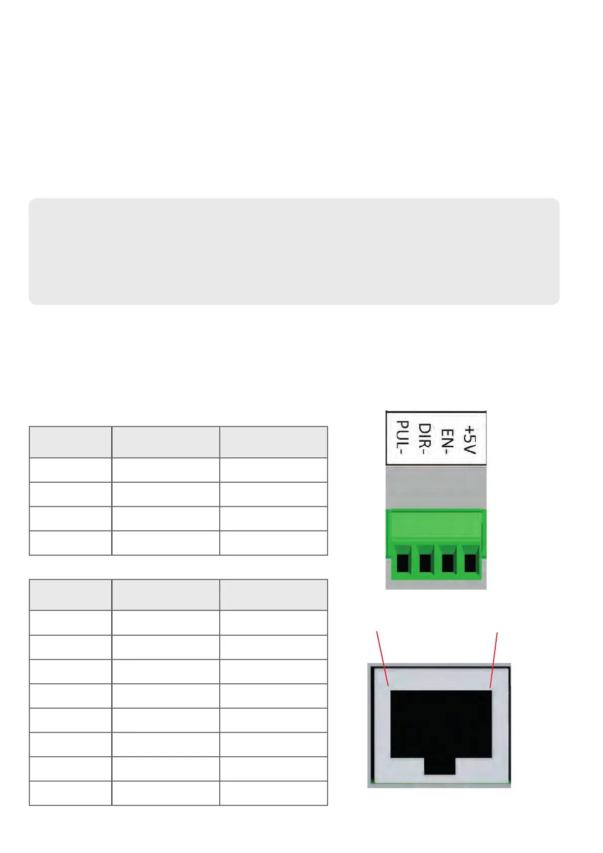
1 2 3 4
30
Please refer to the system documentation for selection and parametrization. The outputs pro-
vide step/direction signals with enable signal for X and Z axis. The output stages are FET open-
drain outputs which connect to ground.
Maximum switching voltage: +30V
Maximum switching current: 200mA
Maximum pulse length: 12 microseconds (adjustable)
Connection:
Use either screw terminals or RJ45 jack for connection. The RJ45 connector is compatible with
Rocketronics RJ45 driver adapters and allows clean connection of motor drivers with commer-
cially available Ethernet patch cables.
Terminal assignment screw terminal for X and Z axis:
Pin Function
1 PUL- STEP
2 DIR- DIRECTION
3 EN- ENABLE
4 +5V
CONNECTION MOTORDRIVER
Pin Name Function
1 ENA+ +5V
2 ENA- ENABLE
3 PUL- STEP
4 DIR+ +5V
5 DIR- DIRECTION
6 PUL+ +5V
7 NC NC
8 GND GND (0V)
18