Motor Power
Encoder
Z-Axis driver
X-Axis driver
12V =
E-STOP
Z Limit
X Limit
Z-Axis motor
X-Axis moor
-
-
-
+
+
+
Connection of driver and encoder via Eth-
ernet patch cable is only possible with
RJ45-adapters!
38
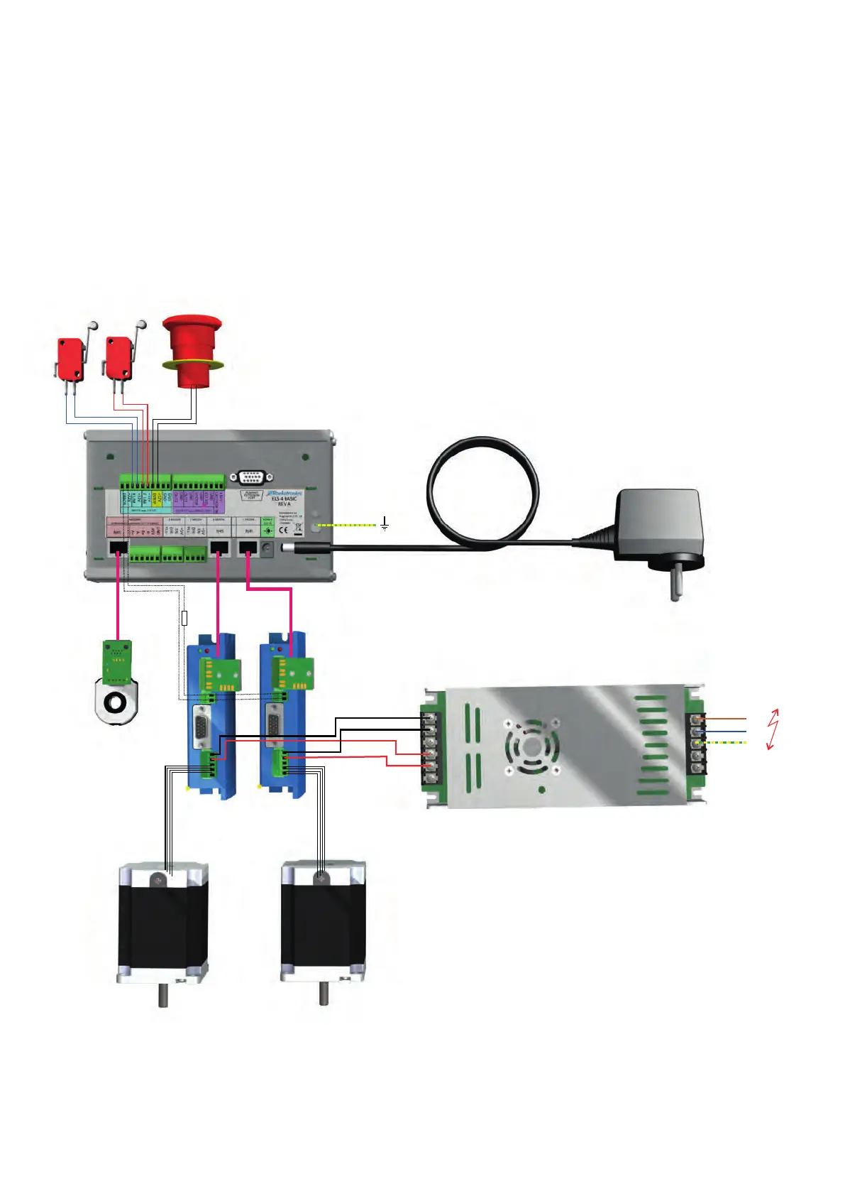
SYSTEM CONNECTION DIAGRAM
The system consists of controller, motor systems, encoder, power supply units and safety ele-
ments is wired as shown below (schematically shown)..
Encoders and motor drivers can be connected directly with patch cables as well as with mul-
ti-core cables. Driver error outputs can be connected to the error input. Please observe the
notes on encoders and motor systems.i