40 Rockwell Automation Publication 520-UM001K-EN-E - August 2021
Chapter 1 Installation/Wiring
13
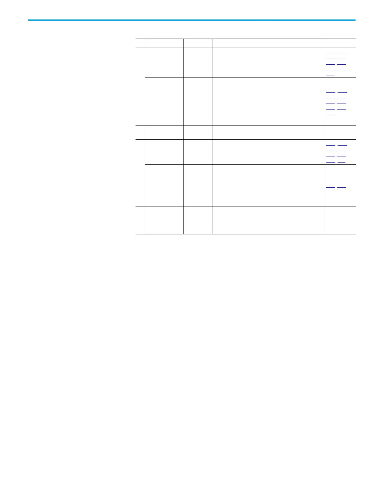
For Series A
0…10V In
(2)
Not Active
For external 0…10V (unipolar) input supply or potentiometer
wiper.
Input impedance:
Voltage source = 100 kΩ
Allowable potentiometer resistance range = 1...10 kΩ
P047, P049,
t062, t063,
t065, t066,
t093, A459,
A471
For Series B
Analog Input
Not Active
External analog input supply, selectable by Analog Input
jumper. Default is 0…10V (unipolar) input supply or
potentiometer wiper.
Input impedance:
Voltage source = 100 kΩ
Allowable potentiometer resistance range = 1...10 kΩ
Change Analog Input jumper to 4…20 mA for external 4…20
mA input supply. Input impedance = 250 Ω
P047
, P049,
t062
, t063,
t065, t066,
t093, A459,
A471
14 Analog Common –
Return for the analog I/O. Electrically isolated (along with the
analog I/O) from the rest of the drive.
–
15
For Series A
4…20 mA In
(2)
Not Active
For external 4…20 mA input supply.
Input impedance = 250 Ω
P047, P049,
t062, t063,
t065, t066,
A459, A471
For Series B
Analog Output
OutFreq 0…10
The default analog output is 0…10V. To convert a current
value, change the Analog Output jumper to 0…20 mA.
Program with t088 [Analog Out Sel]. Maximum analog value
can be scaled with t089 [Analog Out High].
Maximum Load:
4…20 mA = 525 Ω (10.5V)
0…10V = 1 kΩ (10 mA)
t088, t089
C1 C1 –
This terminal is tied to the RJ-45 port shield. Tie this
terminal to a clean ground in order to improve noise
immunity when using external communication peripherals.
–
C2 C2 – This is the signal common for the communication signals. –
(1) Setting is specific to PowerFlex 525 drives only.
(2) Only one analog frequency source may be connected at a time. If more than one reference is connected at the same time, an
undetermined frequency reference will result.
Control I/O Terminal Designations (Continued)
No. Signal Default Description Parameter

 Loading...


