Rockwell Automation Publication 520-UM001K-EN-E - August 2021 39
Chapter 1 Installation/Wiring
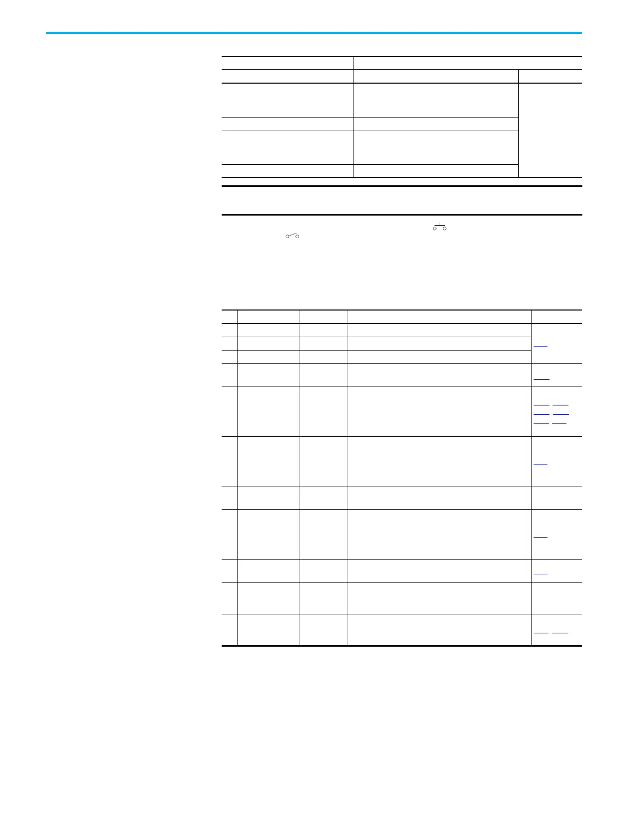
(2) Two wire control shown. For three wire control use a momentary input on I/O Terminal 02 to command a start. Use a
maintained input for I/O Terminal 03 to change direction.
(3) Analog output (terminal 15) is only available on PowerFlex 523 series B drive, and requires firmware 3.001 and later to
configure the analog output parameters (t088, t089, and t090).
(4) Potentiometer connection is only applicable when the 0
…10V setting (default) is selected for jumper J4.
(5) Only one analog frequency source may be connected at a time. If more than one reference is connected at the same time, an
undetermined frequency reference will result.
Start Method Stop Method
t062, t063 [DigIn TermBlk xx] I/O Terminal 01 Stop Normal Stop
48 “2-Wire FWD”
t064 [2-Wire Mode] is set to:
• 0, 1, or 2 = Coast
• 3 = per P045 [Stop Mode]
Per P045
[Stop Mode]
49 “3-Wire Start” Per P045 [Stop Mode]
50 “2-Wire REV”
t064 [2-Wire Mode] is set to:
• 0, 1, or 2 = Coast
• 3 = per P045 [Stop Mode]
51 “3-Wire Dir” Per P045 [Stop Mode]
IMPORTANT
The drive is shipped with a jumper installed between I/O Terminals 01 and 11.
Remove this jumper when using I/O Terminal 01 as a stop or enable input.
Control I/O Terminal Designations
No. Signal Default Description Parameter
R1 Relay N.O. Fault Normally open contact for output relay.
t076
R2 Relay Common Fault Common for output relay.
R3 Relay N.C. Fault Normally closed contact for output relay.
01 Stop Coast
Three wire stop. However, it functions as a stop under all
input modes and cannot be disabled.
P045
(1)
02
DigIn TermBlk 02/
Start/Run FWD
Run FWD
Used to initiate motion and also can be used as a
programmable digital input. It can be programmed with t062
[DigIn TermBlk 02] as three wire (Start/Dir with Stop) or two
wire (Run FWD/Run REV) control. Current consumption is 6
mA.
P045, P046,
P048, P050,
A544, t062
03
DigIn TermBlk 03/
Dir/Run REV
Run REV
Used to initiate motion and also can be used as a
programmable digital input. It can be programmed with t063
[DigIn TermBlk 03] as three wire (Start/Dir with Stop) or two
wire (Run FWD/Run REV) control. Current consumption is 6
mA.
t063
04 Digital Common –
Return for digital I/O. Electrically isolated (along with the
digital I/O) from the rest of the drive.
–
05
DigIn TermBlk 05/
Pulse In
Preset Freq
Program with t065 [DigIn TermBlk 05].
Also functions as a Pulse Train input for reference or speed
feedback. Requires an NPN pulse input. The maximum
frequency is 100 kHz. Current consumption is
6 mA.
t065
06 DigIn TermBlk 06 Preset Freq
Program with t066 [DigIn TermBlk 06].
Current consumption is 6 mA.
t066
11 +24V DC –
Referenced to Digital Common.
Drive supplied power for digital inputs.
Maximum output current is 100 mA.
–
12 +10V DC –
Referenced to Analog Common.
Drive supplied power for 0...10V external potentiometer.
Maximum output current is 15 mA.
P047
, P049

 Loading...


