Rockwell Automation Publication 520-UM001K-EN-E - August 2021 55
Chapter 1 Installation/Wiring
200...240V AC (-15%, +10%) – 3-Phase Input with External EMC Filter, 0...230V 3-Phase Output
A Yes Yes Output only No No Input/Output
B Yes Yes Output only No No Input/Output
C Yes Yes Output only No No Input/Output
DYes Yes No No No Input only
E Yes Yes Output only No No Input only
380...480V AC (-15%, +10%) – 3-Phase Input with External EMC Filter, 0...460V 3-Phase Output
A Yes Yes No No No Input/Output
B Yes Yes No No No Input/Output
CYes Yes No No No Input only
D Yes Yes Output only No No Input/Output
E Yes Yes No Yes No Input/Output
380...480V AC (-15%, +10%) – 3-Phase Input with Internal EMC Filter, 0...460V 3-Phase Output(1)
A * * * No No Input/Output
B * * * No No Input/Output
C * * * No No Input/Output
D * * * No No Input/Output
E * * * No No Input/Output
525...600V AC (-15%, +10%) – 3-Phase Input with External EMC Filter, 0...575V 3-Phase Output
A Yes Yes No No No Input/Output
B Yes Yes No No No Input/Output
C Yes Yes No No No Input/Output
D Yes Yes No No No Input/Output
E Yes Yes No Yes No No
(1) Minimum EMC enclosure dimension (60 x 55 x 80 cm) with a shielding attenuation of at least 92 dB.
(2) An (*) indicates that EMC requirements are not met.
Additional Installation Requirements (Continued)
Frame
Size
Category C1 Category C2
Enclosure
(1)
Conduit or Shielded
Cable @ Input
EMC Cores Required
(Included with product)
Enclosure
(1)
Conduit or Shielded
Cable @ Input
EMC Cores Required
(Included with product)
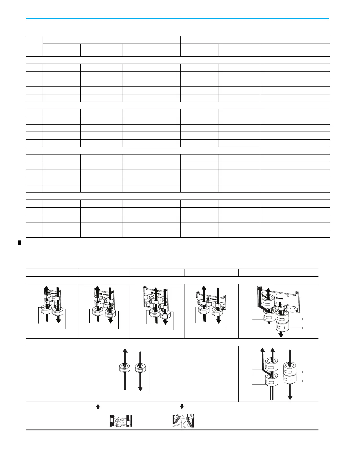
Recommended Placement of EMC Cores
Frame A Frame B Frame C Frame D Frame E
With optional EMC plate (25-EMC-Fx)
Without EMC plate
CORE-E-1
CORE-E-2
CORE-E-3
CORE-E-4
Ground
cable
CORE-E-1
CORE-E-2
CORE-E-3
CORE-E-4
Ground
cable
Shows contact to
shielded layer
Secure EMC core by
using cable/zip ties
Output cable from drive (Shielded)
Input cable to drive (Shielded or Unshielded)

 Loading...


