118 Rockwell Automation Publication 7000-UM202H-EN-P - November 2023
Chapter 2 Power Component Definition and Maintenance
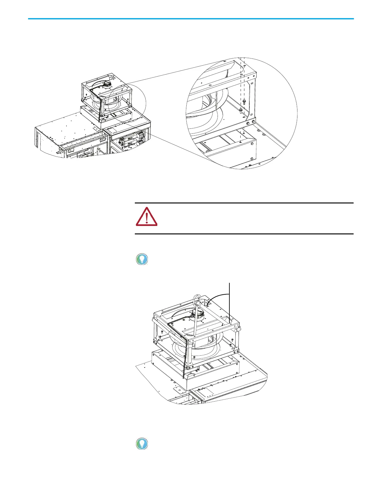
4. Remove and retain the main fan assembly M8 x 25 hardware from the fan
mounting flange.
5. Attach the slings to the load-rated overhead crane, hoist, or similar lifting
device.
6. Loop the slings through either side of the main fan assembly housing.
7. Slowly test lift the main fan assembly a short distance off the cabinet and
observe the orientation of the load. Ensure that the main fan assembly is
supported in an upright orientation.
ATTENTION: If you are not able to use a crane, hoist, or lifting device, you
must have at least two people to lift the main fan assembly. Wear
appropriate personal protection equipment (PPE), including gloves, safety
glasses, and safety shoes.
To reduce tension on the rigging and compression to the main fan
assembly, ensure that the angle between the slings and vertical plane
does not exceed 40°.
If necessary, lower the load to the floor and adjust the rigging lengths to
compensate for any unequal weight distribution to achieve an upright
orientation.

 Loading...


