Rockwell Automation Publication 7000-UM202H-EN-P - November 2023 119
Chapter 2 Power Component Definition and Maintenance
8. Lift and transport the main fan assembly from the top of the cabinet.
9. Remove and retain the hardware that attaches the fan mounting flange
to the top of the cabinet.
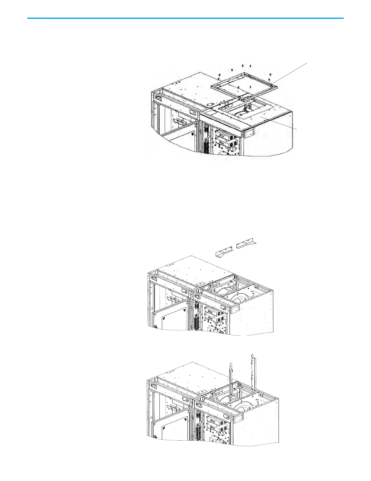
10. Remove and retain the M6 x 20 (6 N•m [4 lb•ft]) hardware that attaches
the top plate to the cabinet and remove the top plate.
Remove the Redundant Ziehl-Abegg Fan Assembly
Follow these instructions to remove the redundant Ziehl-Abegg fan assembly.
1. Remove and retain the hardware (6 x M8 bolt, 4 x M8 nut) from two
horizontal support brackets.
2. Remove and retain the hardware (4 x M6 nut) from two vertical support
brackets.
Top Plate
Fan Mounting Flange
M8 bolt/nut:
25 N•m (18 lb•ft)

 Loading...


