120 Rockwell Automation Publication 7000-UM202H-EN-P - November 2023
Chapter 2 Power Component Definition and Maintenance
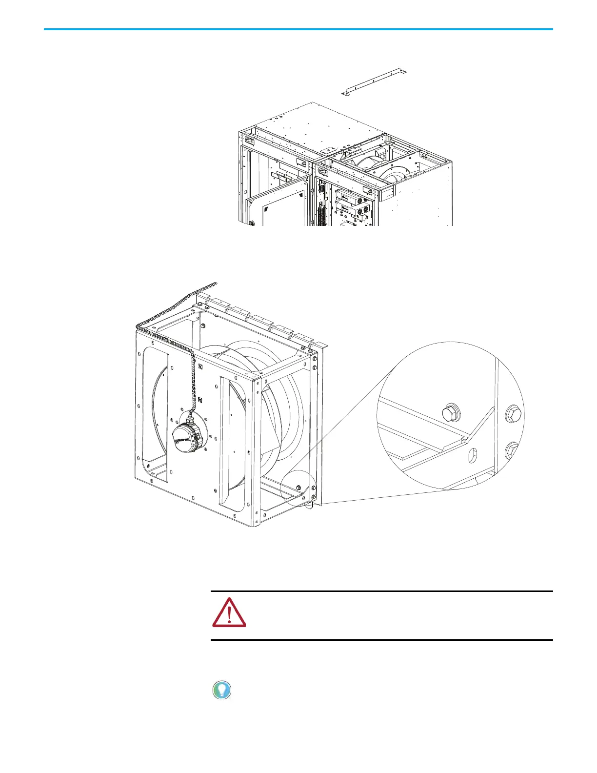
3. Remove and retain the hardware (2 x M8 bolt, 4 x M8 nut) from one
horizontal support bracket.
4. Remove the redundant fan assembly power cables from the LV panel
entry point back along the length of the low voltage wireway.
5. Remove the four M8 bolts (25 N•m [18 lb•ft]) that affix the redundant fan
to the cabinet.
6. Attach slings to a load-rated overhead crane, hoist, or similar lifting
device.
• GR45 fan: 52 kg (99 lb)
• GR56 fan: 80 kg (176 lb)
7. Loop the slings through the corner posts on the front and rear of the
redundant fan assembly.
M8 bolt/nut:
25 N•m (18 lb•ft)
M6 bolt/nut:
10 N•m (7 lb•ft)
ATTENTION: If you are not able to use a crane, hoist, or lifting device, you
must have at least two people to lift the main fan assembly. Wear
appropriate personal protection equipment (PPE), including gloves, safety
glasses, and safety shoes.
To reduce tension on the rigging and compression to the redundant fan
assembly, ensure that the angle between the slings and vertical plane
does not exceed 40°.

 Loading...


