Rockwell Automation Publication 7000-UM202H-EN-P - November 2023 121
Chapter 2 Power Component Definition and Maintenance
8. Slowly lift the redundant fan assembly out of the cabinet. The the
redundant fan assembly must be supported in an upright orientation.
9. Install the new redundant fan in the cabinet in reverse order of removal.
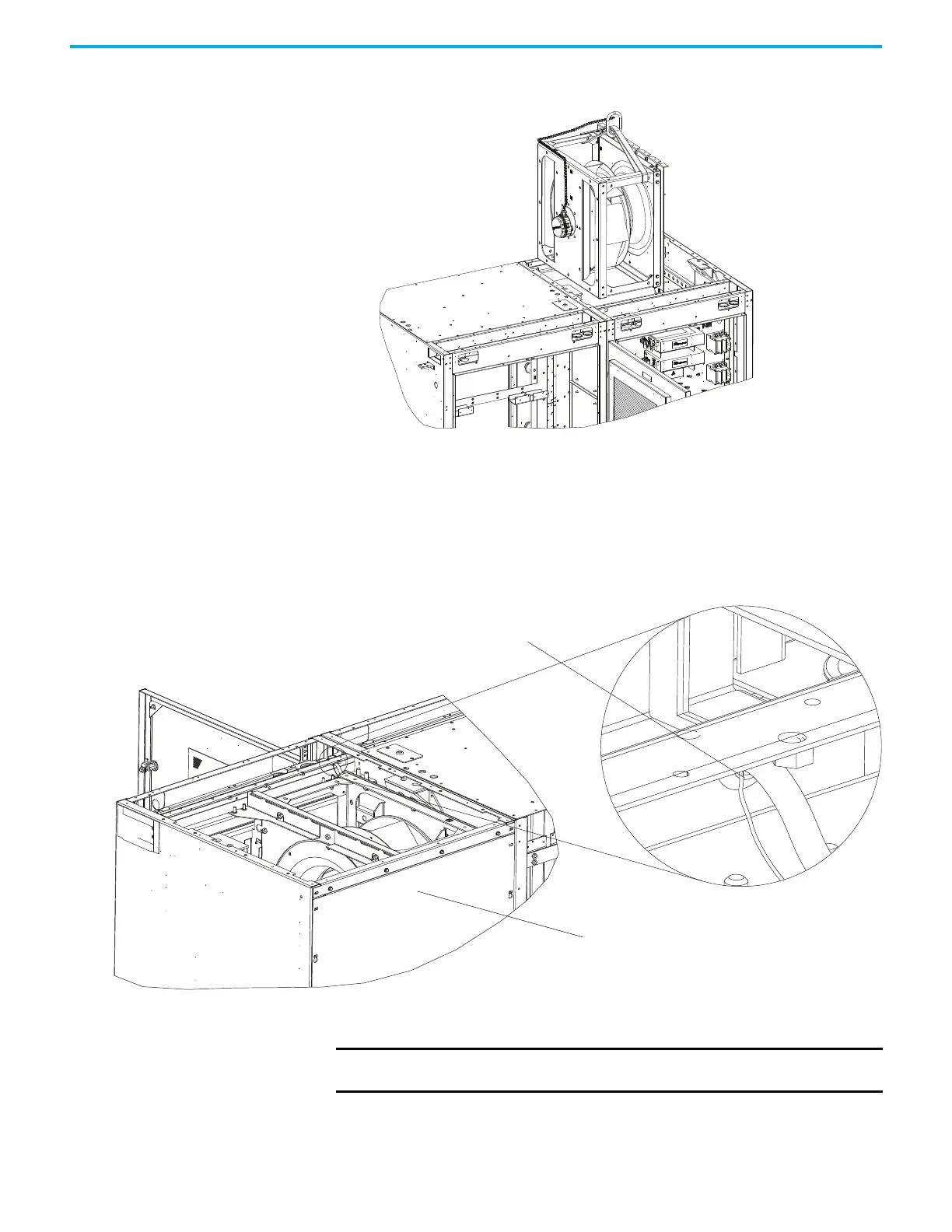
Route the Redundant Fan Assembly Power Cables
Follow these steps to route the redundant fan assembly power cables to the
terminal blocks in the low voltage panel.
1. Insert the redundant fan assembly power cables down through the
redundant fan cable exit point into the low voltage wireway.
2. Route the redundant fan assembly power cables along the length of the
low voltage wireway to the LV panel entry point.
Insert Power Cables Here
Common Mode
Choke Cabinet
IMPORTANT Use zip ties at several points so the redundant fan assembly power
cables do not move.

 Loading...


