EN
50
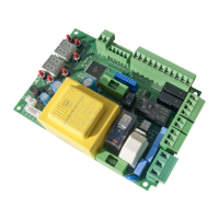
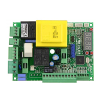
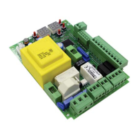
6 Description of connections
Figures show connection diagrams.
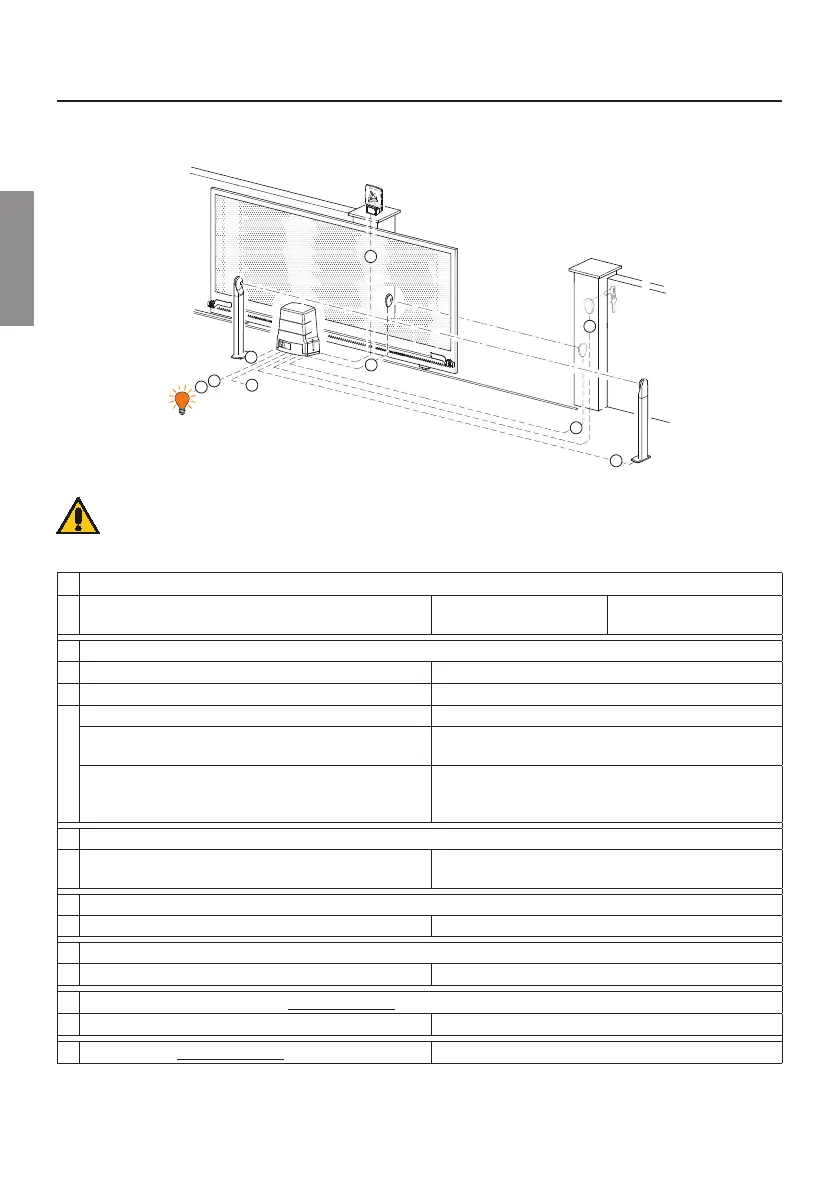
6.1 Typical installation
1
6
7
2
2
4
3
3
5
It is the installer's responsibility to verify the adequacy of the cables in
relation to the devices used in the installation and their technical
characteristics.
CONNECTING CONTROL UNIT TO MAINS ELECTRICITY
1
Power supply 230 V~ ±10%
(115 V~ ±10% H70/104AC/115-H70/105AC/115)
\QQ² (max 15 m) \QQ² (max 30 m)
CONNECTING CONTROL PANEL TO ACCESSORIES
2 Photocells - Receiver F2ES/F2S \QQ² (max 20 m)
3 Photocells - Transmitter F2ES/F2S \QQ² (max 20 m)
4
Key selector R85/60 \QQ² (max 20 m)
Keypad H85/TDS - H85/TTD
(connecting to H85/DEC - H85/DEC2)
\QQ
2
(max 30 m)
H85/DEC - H85/DEC2
(connecting to control unit)
\QQ
2
(max 20 m)
The number of conductors increases when using more
than one output contact on H85/DEC - H85/DEC2
CONNECTING CONTROL PANEL TO FLASHING LIGHT
5
LED Flashing light R92/LED230 - FIFTHY/230
Power supply 230 V~ by LED (40 W max)
2x1 mm² (max 10 m)
CONNECTING CONTROL PANEL TO GATE OPEN INDICATOR
6 Power supply 24 V~ (2 W max) \QQ² (max 20 m)
CONNECTING CONTROL PANEL TO COURTESY LIGHT
7 Power supply 230 V~ (100 W max) 2x1 mm² (max 20 m)
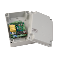
CONNECTING CONTROL PANEL H70/105AC/BOX TO MOTORS
Motor \QQ² (max 20 m)
Limit switches H70/105AC/BOX \QQ² (max 20 m)
 Loading...