EN
54
10 Display function mode
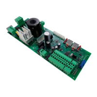
• Parameter display mode
PARAMETER
PARAMETER
VALUE
See chapter 13 for detailed descriptions of parameters.
• Command and safety device status display mode
COMMAND STATUS SAFETY DEVICE STATUS
AP PED
ORO
FT1
COS1
COS2
FT2
FA
FC
PP
CH
POWER ENC SB STOP
COMMAND STATUS:
The command status indicators on the display (segments
%4 ! STIR 44 ! WXIT QSHI ', ! GPSWI 4)( ! TEVXMEP
opening 363! GPSGO are normally off. They illuminate
[LIR E GSQQERH MW VIGIMZIH IK [LIR E WXIT QSHI
GSQQERHMWVIGIMZIHXLIWIKQIRX44MPPYQMREXIW
SAFETY DEVICE STATUS:
The safety device status indicators on the display
(segments FT1/FT2=photocells '37'37 ! sensing
edge *%! KEXI STIR PMQMX W[MXGLIW *'!KEXI GPSWI PMQMX
W[MXGLIW )2'! )RGSHIV 7&! 6IPIEWI W]WXIQ JSV
H70/104AC) EVIRSVQEPP]SR-JERMRHMGEXSVMWSJJXLIVIPEXMZIHIZMGIMWMREPEVQWXEXISVMWRSXGSRRIGXIH8LIER
MRHMGEXSVMWƽEWLMRKXLIVIPEXMZIHIZMGILEWFIIRHMWEFPIH[MXLEWTIGMƼGTEVEQIXIV
• TEST mode
8LI8)78QSHIMWYWIHXSXIWXEGXMZEXMSRSJXLIGSQQERHWERHWEJIX]HIZMGIW[MXLZMWYEPGSRƼVQEXMSR
8SEGXMZEXIXLIQSHITVIWWXLI8)78FYXXSR[MXLXLIEYXSQEXMGKEXIW]WXIQEXVIWX-JXLIKEXIMWQSZMRKTVIWWMRK
TEST stops the gate. Pressing the button again enables TEST mode.
-JXLIƽEWLMRKPMKLXERHXLIKEXISTIRMRHMGEXSVPEQTMPPYQMREXIJSVSRIWIGSRHIEGLXMQIEGSRXVSPMWYWIHSVEWEJIX]
device is activated.
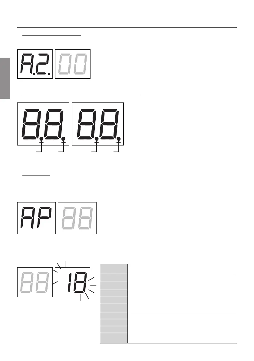
The command signal status is shown on the left hand side of the display
JSVWIGSRHW320=[LIRXLIVIWTIGXMZIGSQQERHWMKREPMWEGXMZI%4
',444)36*SVI\EQTPIMJXLIKEXISTIRGSQQERHMWEGXMZEXIHXLI
letters AP appear on the display.
The status of the safety devices/inputs is shown on the right hand side of the display. The number of the terminal
VIPEXMZIXSXLIWEJIX]HIZMGIMREPEVQWXEXIƽEWLIW
;LIRXLIKEXIMWGSQTPIXIP]STIRSVGSQTPIXIP]GPSWIH)$ or )& is shown on the display to indicate that the gate has
reached the gate open limit switch )$ or gate closed limit switch )&.
)\EQTPI7834GSRXEGXMREPEVQWXEXI
2S WEJIX] HIZMGI MR EPEVQ WXEXI ERH RS PMQMX W[MXGL
activated
6E(Sb)
Release handle or lock open.
STOP
Sensing edge COS1
Sensing edge COS2
Photocell FT1
Photocell FT2
IH
More than 3 limit switches activated
ID
Gate completely open / Gate open limit switch activated
I&
Gate completely closed / Gate closed limit switch
activated
 Loading...