System Fault Screen
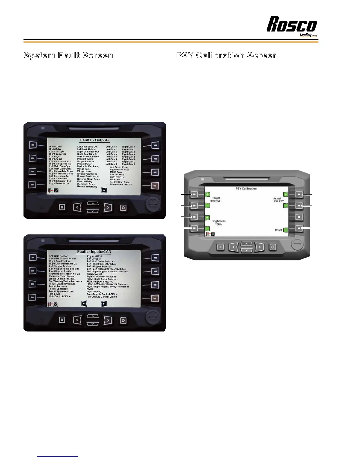
The fault screens inform the operator that a problem
exists. (Figures 4-18 and 4-19) These screens
indicate system faults, joystick or sensor problems,
valve or pump output problems and loss of controller
network. If there is an active problem, a red box will
illuminate next to the affected component listed. Use
the left and right arrow keys to scroll between the two
system fault screens.
Figure 4-18. System Faults (Outputs) Screen
Figure 4-19. System Faults (Inputs/CAN) Screen
PSY Calibration Screen
Proper PSY (pounds per square yard) calibration
delivers a chip seal that is uniform without excessive or
insufcient aggregate. On the PSY calibration screen,
enter the target PSY rate using the + and - buttons (1
and 2) on the left side of the display unit. (Figure 4-20)
Then determine the aggregate application rate using
the procedure described on Page 4-18. Enter that PSY
number into the “actual” rate using the + and - buttons
(5 and 6) on the right side of the display unit. Press the
Reset button (7) to reset the PSY calibration.
This screen also allows the operator to set the digital
display screen brightness using Buttons 3 and 4.
Pressing the right arrow key scrolls to the Totals/Auto
Resume screen. (Figure 4-21)
1
2
3
4
5
6
7
Figure 4-20. PSY Calibration Screen
1 - Target PSY Rate Increase
2 - Target PSY Rate Decrease
3 - Screen Brightness Increase
4 - Screen Brightness Decrease
5 - Actual PSY Rate Increase
6 - Actual PSY Rate Decrease
Operation
Rosco CSV Variable Width Chip Spreader4-14