DEF Tank Filter
The DEF tank lter should be cleaned or replaced every
2000 hours, or every two years, whichever is rst. The
lter is the rst point of contact with foreign elements.
To clean or replace the DEF tank lter, remove the DEF
header tank assembly using the following procedures.
The DEF lines are connected using quick-release
ttings and must be disconnected in the order
described below. (Figure 5-18)
NOTE: It is imperative that you disconnect the
plumbing from the header in the exact order
described below to prevent accidental DEF
contamination of the electrical connector.
Wear eye protection, gloves and
appropriate protective clothing to avoid injury. The
coolant lines connect to the after treatment dosing
unit are hot and under pressure. DO NOT disconnect
while the engine is running or before the system has
purged and cooled down after shutting down the
engine. Disconnecting the coolant lines before the
system cools down may cause coolant to spray and
burn skin on contact.
1. Complete Steps 1 - 4 to prepare machine for DEF
system maintenance.
2. Place a container under the DEF tank as a small
amount of DEF may drain from the coolant lines
when disconnected. (Dispose of the uid in
accordance with environmental regulations.) DO
NOT ush the coolant.
3. Use a clean, damp cloth to wipe the unit to reduce
the risk of contamination entering the DEF tank.
Wipe away any spilled DEF while servicing the DEF
tank lter.
1
2
3
4
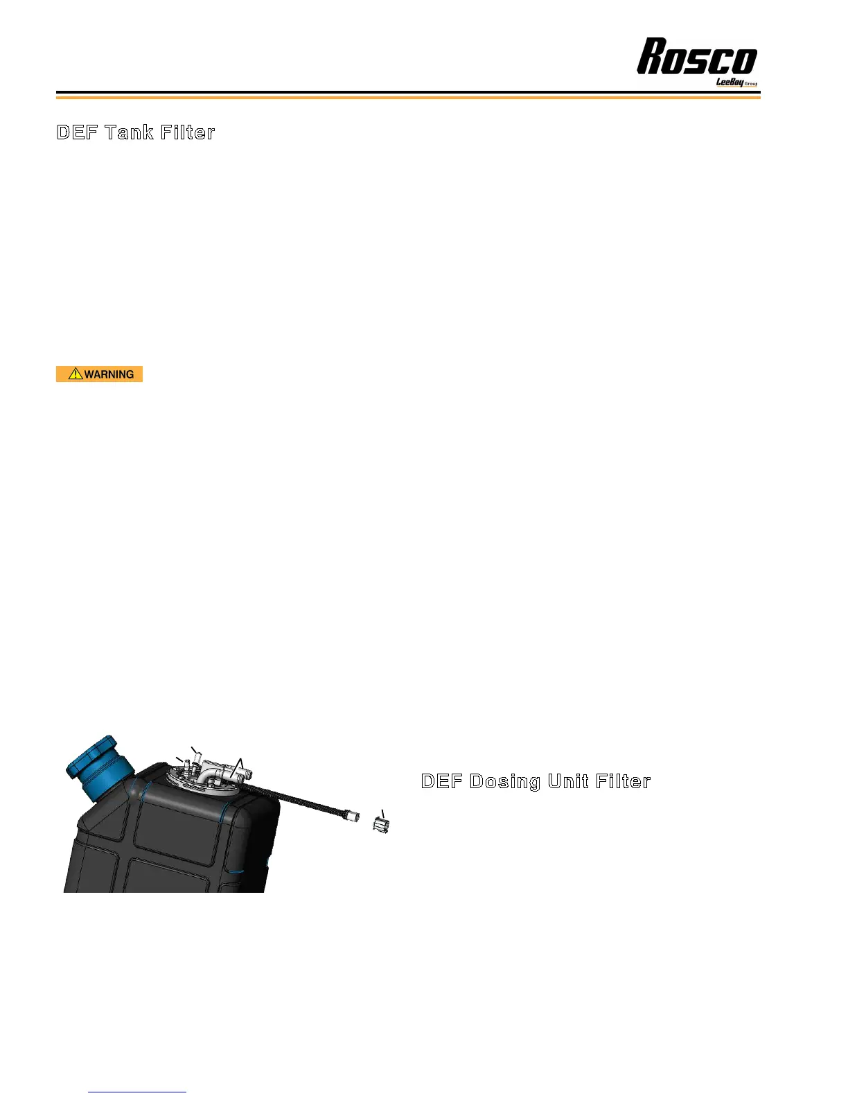
Figure 5-18. DEF Tank Header Assembly
1 - Suction DEF Connector
2 - DEF Connector
3 - Coolant Connectors
4 - Electrical Connector
4. Disconnect the coolant connectors and cap the
lines to prevent contamination or DEF leakage.
Figure 5-18) (You can also use a pair of coolant
hose pinch-off pliers to clamp the lines. Make sure
the tank coolant hose material is exible enough.)
DO NOT drain the cooling system. DO NOT spill any
coolant into the DEF tank.
5. Disconnect the DEF connector.
6. Disconnect the suction DEF connector.
7. Disconnect the back-ow DEF connector.
8. Disconnect the electrical connector by pressing the
top of the tting.
9. Remove the header from the tank by removing the
six bolts on the metal ring separating the header
from the tank. Slowly and carefully lift the header
out of the DEF tank, exposing the lter unit, to avoid
damaging the lter or other components.
10. Remove the clip, pull the lter cartridge out and
inspect for cracks, damage and contamination
or debris. Clean the lter and reinsert, unless
replacing the lter at service interval or if debris or
damage is evident:
• Discard the lter element and O-ring in
accordance with environmental regulations and
replace with a new lter element.
• Also inspect the after-treatment DEF dosing unit
lter after replacing the tank lter. (Figure 5-19)
11. Lubricate the O-rings with clean DEF uid and install
the new lter element (O-ring side facing outward) in
its seated notch location.
12. Reinstall the lter cartridge into the DEF tank.
13. Reinstall the tank lter header in reverse order
DEF Dosing Unit Filter
The DEF dosing unit lter prevents foreign objects that
may be suspended in the DEF from entering the dosing
system, which draws DEF from the tank, pressurizes
it, and delivers the DEF through a dosing valve. Any
unused DEF is then routed back to the tank. The DEF
dosing unit lter should be replaced every 4500 hours
or three years, whichever comes rst. It is located on
the left inside the rear access panel on the driver’s side.
Maintenance
Rosco CSV Variable Width Chip Spreader5-16