Reference Manual
00809-0100-4809, Rev DA
Appendix A: Specifications and Reference Data
September 2015
172
Specifications and Reference Data
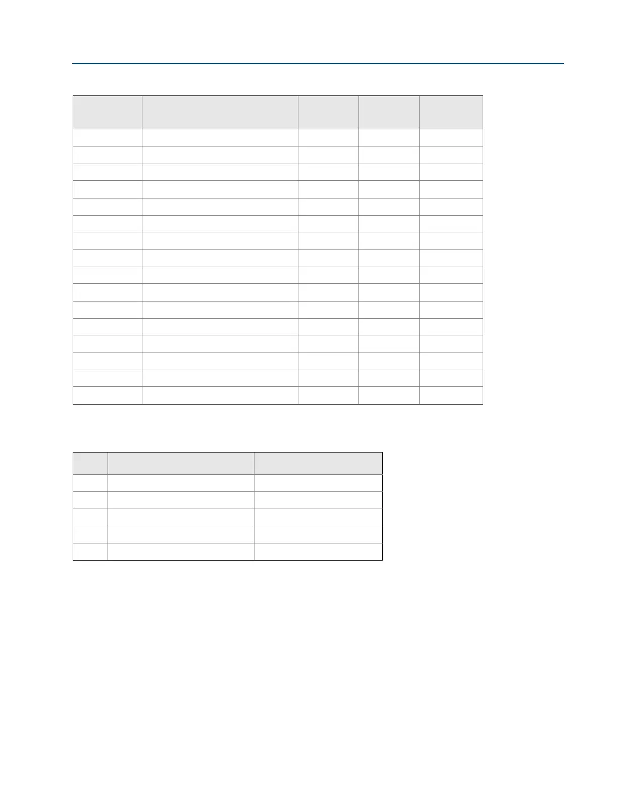
Annubar sensor type specification chart
Instrument connection temperature ranges
Option code Mounting type/pressure class
Flanged Main steam
Gear-drive
Flo-Tap
A1 150# RF ANSI X X
A3 300# RF ANSI X X
A6 600# RF ANSI X X
AN
(1)
1. Remote mount only.
900# RF ANSI X
AF
(1)
1500# RF ANSI X
AT
(1)
2500# RF ANSI X
D1 DIN PN 16 X X
D3 DIN PN 40 X X
D6 DIN PN 100 X X
R1 150# RTJ flange X X
R3 300# RTJ flange X X
R6 600# RTJ flange X X
RN
(1)
900# RTJ flange X
RF
(1)
1500# RTJ flange X
RT
(1)
2500# RTJ flange X
00
(1)
Main steam packing gland X
Table 25. Minimum/Maximum Temperature Range
Code
Description
Temperature
G1 Needle valves, Carbon Steel –20 to 550 °F (–29 to 288 °C)
G2 Needle valves, Stainless Steel –20 to 1000 °F (–29 to 538 °C)
G3 Needle valves, Alloy C-276 –20 to 1000 °F (–29 to 538 °C)
G5 OS&Y gate valve, Carbon Steel –20 to 800 °F (–29 to 427 °C)
G6 OS&Y gate valve, Stainless Steel –20 to 850 °F (–29 to 454 °C)