Reference Manual
00809-0100-4809, Rev DA
Appendix A: Specifications and Reference Data
September 2015
193
Specifications and Reference Data
2 2 – 150#
4.13
(104.9)
11.25
(285.8)
24.44
(620.8)
21.20
(538.5)
C +7.10
(180.3)
12.56
(319.0)
6.80
(172.7)
2 2 – 300#
4.38
(111.3)
13.00
(330.2)
24.44
(620.8)
21.20
(538.5)
C +7.10
(180.3)
12.56
(319.0)
7.05
(179.1)
2 2 – 600#
4.75
(120.7)
16.38
(416.0)
24.44
(620.8)
21.20
(538.5)
C +7.10
(180.3)
12.56
(319.0)
7.05
(179.1)
2 DN50/PN16
3.40
(86.4)
Customer
Supplied
24.44
(620.8)
21.20
(538.5)
C +7.10
(180.3)
12.56
(319.0)
7.05
(179.1)
2 DN50/PN40
3.52
(89.4)
Customer
Supplied
24.44
(620.8)
21.20
(538.5)
C +7.10
(180.3)
12.56
(319.0)
7.05
(179.1)
2 DN50/PN100
4.30
(109.2)
Customer
Supplied
24.44
(620.8)
21.20
(538.5)
C +7.10
(180.3)
12.56
(319.0)
7.05
(179.1)
3 3 – 150#
4.63
(117.6)
12.75
(323.9)
26.37
(669.8)
23.14
(587.8)
C +7.10
(180.3)
14.13
(358.9)
7.55
(191.8)
3 3 – 300#
5.00
(127.0)
16.25
(412.8)
26.37
(669.8)
23.14
(587.8)
C +7.10
(180.3)
14.13
(358.9)
7.93
(201.3)
3 3 – 600#
5.38
(136.7)
19.50
(495.3)
26.37
(669.8)
23.14
(587.8)
C +7.10
(180.3)
14.13
(358.9)
7.93
(201.3)
3 DN80/PN16
3.85
(97.8)
Customer
Supplied
26.37
(669.8)
23.14
(587.8)
C +7.10
(180.3)
14.13
(358.9)
7.93
(201.3)
3 DN80/PN40
4.16
(105.7)
Customer
Supplied
26.37
(669.8)
23.14
(587.8)
C +7.10
(180.3)
14.13
(358.9)
7.93
(201.3)
3 DN80/PN100
4.95
(125.7)
Customer
Supplied
26.37
(669.8)
23.14
(587.8)
C +7.10
(180.3)
14.13
(358.9)
7.93
(201.3)
Dimensions are in inches (millimeters).
1. Inserted, C Dimension = Pipe I.D. + Wall Thickness + B + C
I
2. Retracted, C Dimension = 2 ⫻ (Pipe I.D. + Wall Thickness + B) + C
I
3. DIN Valves are not offered.
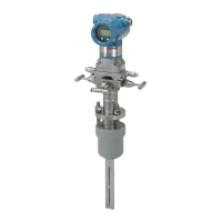
Table 40. 3051CFA Flanged Flo-Tap Annubar Flowmeter Dimensional Data
(1)(2)
Sensor
size
Flange size
and rating
A ± 0.125
(3.2)
B ± 0.25
(6.4)
C
I
(Max)
(Gear
drive)
C
I
(Max)
(Manual)
D (Max) E (Max) F (Max)
 Loading...

