Reference Manual
00809-0100-4809, Rev DA
Appendix A: Specifications and Reference Data
September 2015
211
Specifications and Reference Data
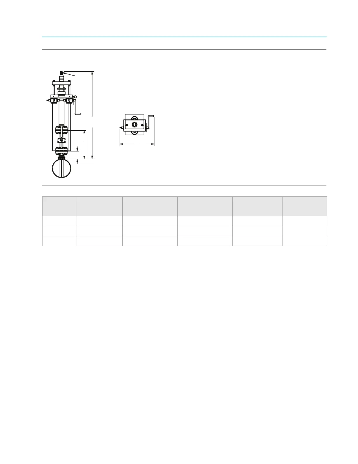
Figure 25. Rosemount 585 Flanged Flo-Tap Annubar Primary Element
Front view Top view
Table 53. 585 Flanged Flo-Tap Annubar Primary Element Dimensional Data
Sensor size
Flange size
and rating
A ± 0.125 (3.2) B ± 0.25 (6.4)
C
1
(Max)
(Gear drive)
D (Max)
44 3 – 150# 4.63 (117,6) 12.75 (323,9) 25.58 (649.7) 23.3 (591,8)
44 3 – 300# 5.00 (127,0) 16.25 (412,8) 25.58 (649.7) 23.3 (591,8)
44 3 – 600# 5.38 (136,7) 19.50 (495,4) 25.58 (649.7) 23.3 (591,8)
Use the appropriate formula to determine C value:
Inserted formula: Pipe I.D. + Wall Thickness + Value B + C
1
(use the Gear drive values for C
1
)
Retracted formula: [2 ⫻ (Pipe I.D. + Wall Thickness + Value B)] + C
1
(use the Gear drive values for C
1
)
Dimensions are in inches (millimeters).