43
Reference Manual
00809-0100-4809, Rev DA
Section 2: Installation
September 2015
Installation
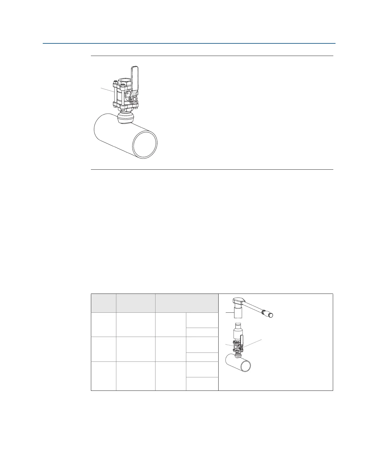
Figure 2-29. Install the Isolation Valve
A. Isolation valve
Step 4: Mount the drilling machine and drill hole
Drilling machine is not provided with the assembly.
1. Determine the drill hole size based on the sensor size or sensor width.
2. Mount the drilling machine to the isolation valve.
3. Open the valve fully.
4. Drill the hole into the pipe wall in accordance with the instructions provided by the
drilling machine manufacturer.
5. Fully retract the drill beyond the valve.
Table 2-9. Sensor Size/Hole Diameter Chart
Sensor
size
Sensor
width
Hole diameter
A. Pressure drilling machine
B. Isolation valve is fully open when inserting drill
C. Isolation Valve is fully closed after withdrawing drill
1
0.590-in.
(14.99 mm)
3
/4-in.
(19 mm)
+
1
/32-in.
(0.8 mm)
– 0.00
2
1.060-in.
(26.92 mm)
1
5
/16-in.
(34 mm)
+
1
/16-in.
(1.6 mm)
– 0.00
3
1.935-in.
(49.15 mm)
2
1
/2-in.
(64 mm)
+
1
/16-in.
(1.6 mm)
– 0.00
A

 Loading...


