42
Reference Manual
00809-0100-4809, Rev DA
Section 2: Installation
September 2015
Installation
Step 2: Weld the mounting hardware
Note
Rosemount-supplied mounting includes critical alignment hardware that assists in the correct
drilling of the mounting hole. This significantly reduces problems encountered during insertion.
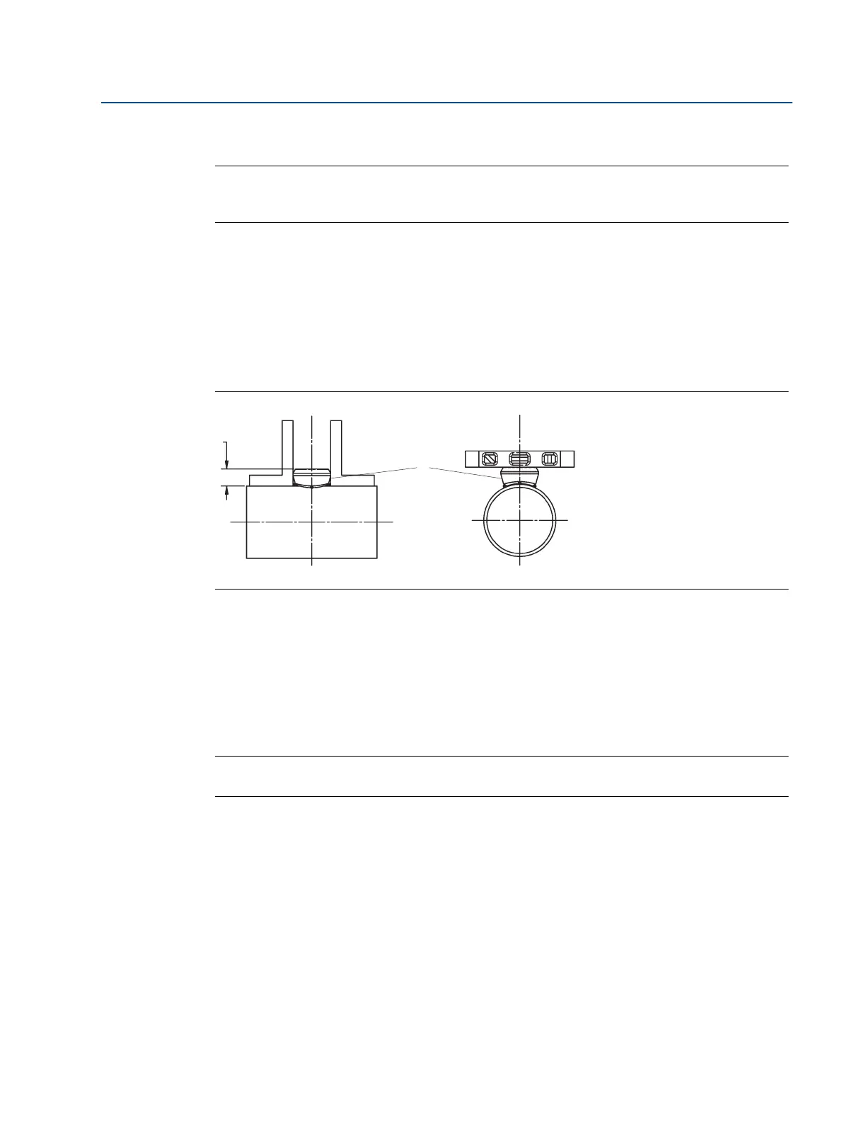
1. At the pre-determined position, place the threadolet on the pipe, gap
1
/16 in. (16 mm)
and place four
1
/4-in. (6-mm) tack welds at 90° increments.
2. Check alignment of the mounting both parallel and perpendicular to the axis of flow. If
the mounting alignment is within tolerances, finish weld per local codes. If outside of
tolerances, make adjustments prior to making the finish weld.
3. To avoid serious burns, allow mounting hardware to cool before continuing.
Figure 2-28. Alignment
A. Tack weld
Step 3: Install the isolation valve
1. Thread the guide nipple into the mounting.
2. Thread the isolation valve into the guide nipple, ensuring that the valve stem is
positioned so that when the Flo-Tap is installed, the insertion rods will straddle the pipe
and the valve handle will be centered between the rods (see Figure 2-29).
Note
Interference will occur if the valve is located inline with the insertion rods.