45
Reference Manual
00809-0100-4809, Rev DA
Section 2: Installation
September 2015
Installation
Step 7: Insert the Annubar sensor
Insert the sensor with one of the two drive options available – manual drive (M) or gear drive
(G).
Manual (not recommended for line sizes above 12-in. {300 mm])
1. Open the isolation valve fully.
2. Rotate drive nuts clockwise (as viewed from the top) as shown in Figure 2-30. The nuts
must be tightened alternately, about two turns at a time to prevent binding caused by
unequal loading.
3. Continue this procedure until the tip of the probe firmly contacts the opposite side of
the pipe.
a. The orange stripes are a visual indication of when the sensor is approaching the
opposite side wall.
b. As the orange stripe approaches the support plate, place a finger above the packing
gland while cranking.
c. Turn the drive nuts an additional
1
/4 to
1
/2 turn to secure the sensor.
Gear drive (G)
1. Fully open the isolation valve.
2. Rotate the crank clockwise. If a power drill with an adapter is used, do not exceed 200
rpm.
a. Continue rotating the crank until the sensor firmly contacts the opposite side of the
pipe. The orange stripes are a visual indication of when the sensor is approaching
the opposite side wall.
b. As the orange stripes approach the support plate, remove the power drill and
continue cranking manually. Place a finger above the packing gland while cranking.
When the movement stops, the sensor is in contact with the opposite side wall.
c. Turn the handle an additional
1
/4 to
1
/2 turn to secure the sensor.
3. Secure the drive by inserting the drive lock pin as shown in Figure 2-31.
Note
Do not place a finger above the packing gland for high temperature applications.
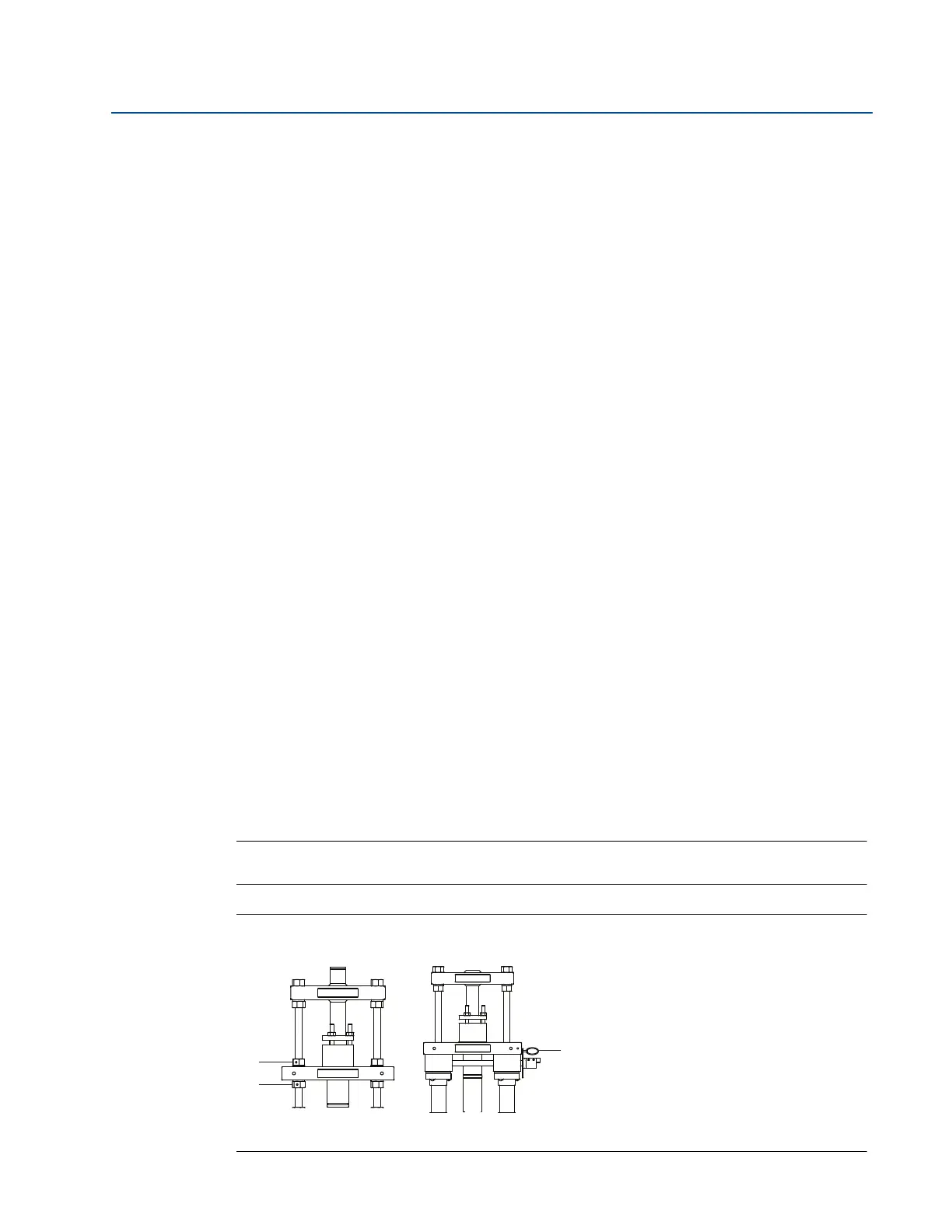
Figure 2-31. Insert Annubar Sensor
Manual drive (M) Gear drive (G)
A. Lock nuts
B. Drive nuts
C. Drive lock pin
A
B
C
 Loading...


