BRP-Rotax
Maintenance Manual
Effectivity 912/914 Series
Edition 1 / Rev. 0
72-00-00
page 35
May 01/2007
d02622
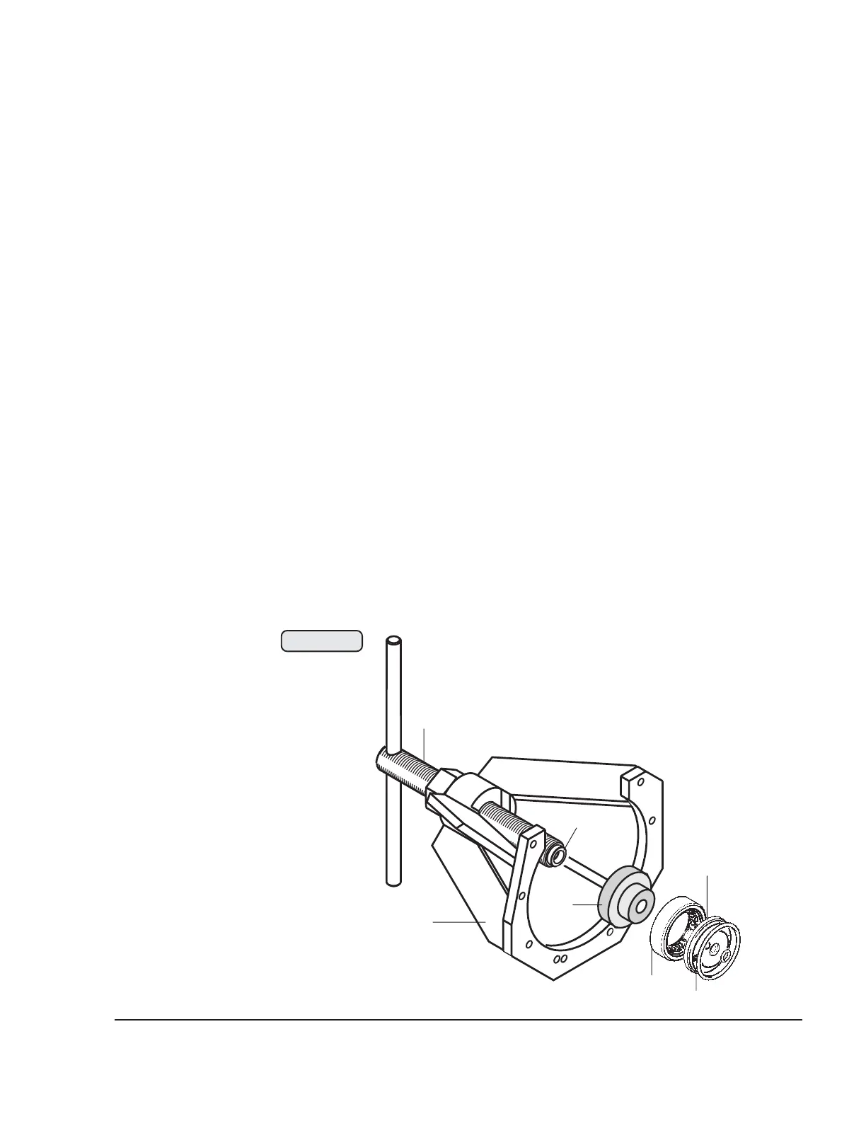
3.9.8) Propeller governor drive installation
See Figs. 72-33 and 72-34.
■ CAUTION : The oil inlet flange must be fitted well aligned and the
O-ring must not be squeezed.
Install needle sleeve and ball bearing as described in 72-00-00 sec.
3.9.9. Grease new O-ring (1) and insert it together with the oil inlet
flange (2) into the crankcase. Take care that both M6 threads are
horizontal and the oil gallery is in a position to let the oil pass. For better
positioning, at first tighten governor flange only slightly with 2 allen
screws M6x20 (12) and oil inlet flange with 2 allen screws M6x16 (13).
Screw extractor (3), part no. 877615, onto the crankcase, place press-
in insert (4), part no. 877590, into roller bearing (5), place on the
centering (6) and press it fully home into the crankcase with the spindle
(7). Fit circlip in groove with its sharp edge towards the outside.
Fit the governor flange (8) again. Fit distance sleeve (9) and new O-ring
(10) 32x4 into the crankcase. Place one O-ring (11) 7x2 into the oil inlet
flange and one into the governor flange and keep them in position with
some grease. Fit the governor flange and attach it to the crankcase with
4 allen screws (12) M6x20 and to the oil inlet flange with 2 allen screws
(13) M6x16.
1
00258
1
2
3
4
5
6
7
Fig. 72-33

 Loading...


