Effectivity 912/914 Series
Edition 1 / Rev. 0
79-00-00
page 27
May 01/2007
d02628
BRP-Rotax
Maintenance Manual
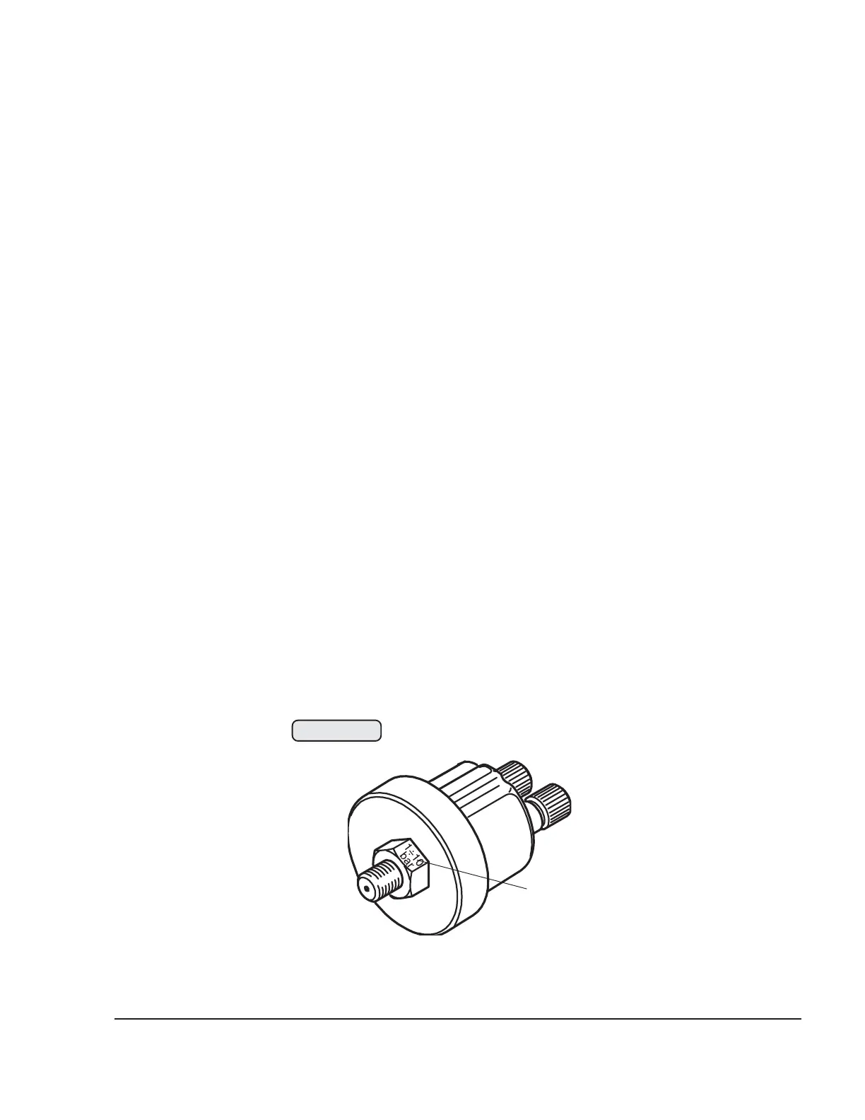
3.9.2) Oil pressure sensor
See Figs. 79-19, 79-20 and 79-21.
The sensor (2) for measurement of the oil pressure is screwed into the
oil pump housing.
The range of the sensor is from 0 to 10 bar (0 to 145 p.s.i) This range
(3) is indicated on the wrench flats of the sensor.
■ CAUTION: For this reason, the pressure range of the display
instrument must be adjusted to the pressure range of
the sensor. If this is not done, an incorrect oil pressure
will be displayed.
The operating pressure must remain within the specified limits. If this
is not the case, check
- the lubrication system (see corresponding Maintenance Manual
(Line Maintenance) for the respective engine type, 912 Series or
914 Series.)
- oil pressure sensor
- indicating instrument
- wiring connections
- sensor cable
◆ NOTE: Grounding connection of the sensor is direct via
the oil pump housing.
07226
3
Fig. 79-20

 Loading...


