Effectivity 914 Series
Edition 1 / Rev. 0
page 43
May 01/2007
d02623
73-00-00
BRP-Rotax
Maintenance Manual
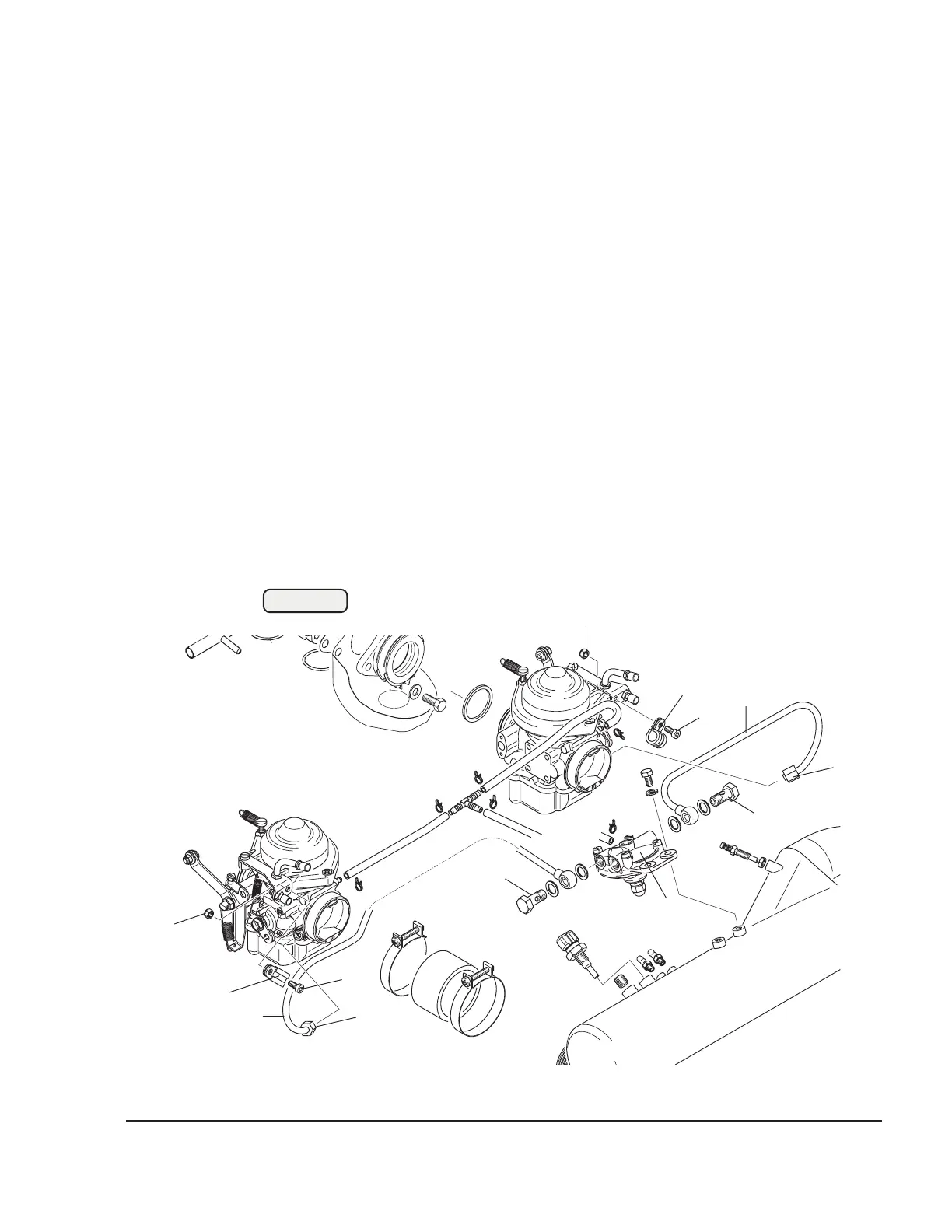
3.4.5) Fuel lines (on 914 Series)
See Figs. 73-37 and 73-38.
Each fuel line (1) is supported by a cable clamp (2) on the carburetors.
The clamps are attached with allen screws M5x12 (3) and lock nuts (4).
Unscrew the banjo bolts (5) on the fuel pressure regulator (7) and the
collar nut (6).
Carry out a visual inspection for damage or wear, paying particular
attention to the formation of any cracks in the area of the connections.
■ CAUTION : When removing fuel lines, support them adequately to
avoid strain or additional load.
Check lines for free passage using compressed air and inspect them
for scuffing marks.
▲ WARNING: Replace damaged fuel lines!
Fig. 73-37
00031
2
1
7
3
1
4
2
3
5
4
2
6
6
5

 Loading...


