EasyManuals Logo

Rotax 912 Series Service Manual

Rotax 912 Series
456 pages
To Next Page IconTo Next Page
To Previous Page IconTo Previous Page
Page #88 background imageLoading...
Page #88 background image
BRP-Rotax
Maintenance Manual
72-00-00
page 20
May 01/2007
Effectivity 912/914 Series
Edition 1 / Rev. 0
d02622
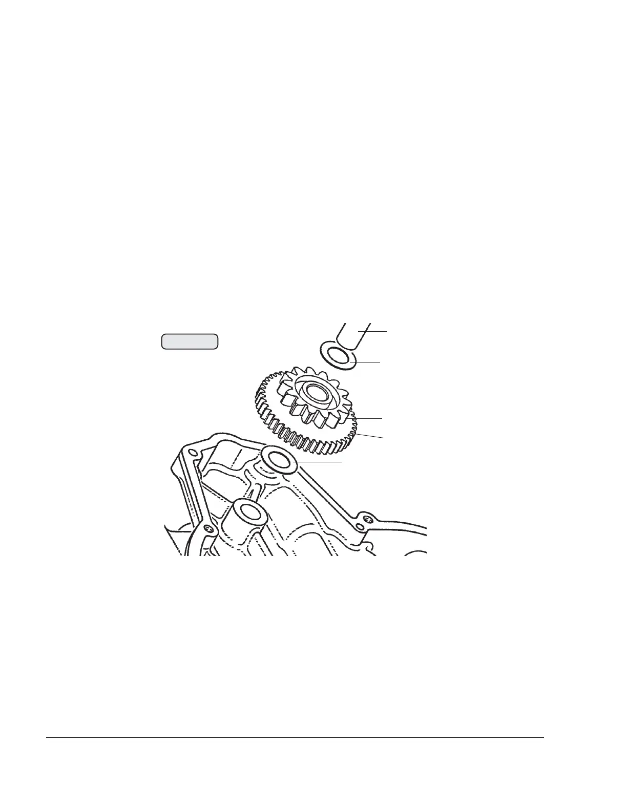
3.7) Reduction gear for electric starter
See Fig. 72-16.
Place thrust washer (1) 12.5/21.5/1 on the crankcase. Place interme-
diate gear (2) in position, oil intermediate gear shaft (3) and push into
position. Place thrust washer (4) 12.5/21.5/1 on top.
Check the geartooth system of the intermediate gear (5). If the gear-
tooth system is deformed, the intermediate gear must be replaced.
â—† NOTE: If the teeth of the intermediate gear are deformed, a
noise will be produced when the engine is started.
00240
3
4
2
1
Fig. 72-16
5

Table of Contents

Other manuals for Rotax 912 Series

Questions and Answers:

Question and Answer IconNeed help?

Do you have a question about the Rotax 912 Series and is the answer not in the manual?

Rotax 912 Series Specifications

General IconGeneral
Redline5800 rpm
TBO2000 hours
Displacement1211 cc
Bore79.5 mm
Stroke61 mm
Power Output80 hp (59.6 kW)
Compression Ratio9.0:1
Fuel TypeAvgas 100LL
Ignition SystemDual electronic ignition
Fuel SystemFuel Injected
Oil SystemDry sump
Engine Type4-cylinder, horizontally opposed, 4-stroke

Related product manuals