EasyManuals Logo

Rotax 912 Series Service Manual

Rotax 912 Series
456 pages
To Next Page IconTo Next Page
To Previous Page IconTo Previous Page
Page #199 background imageLoading...
Page #199 background image
Effectivity 912/914 Series
Edition 1 / Rev. 0
page 13
May 01/2007
d02623
73-00-00
BRP-Rotax
Maintenance Manual
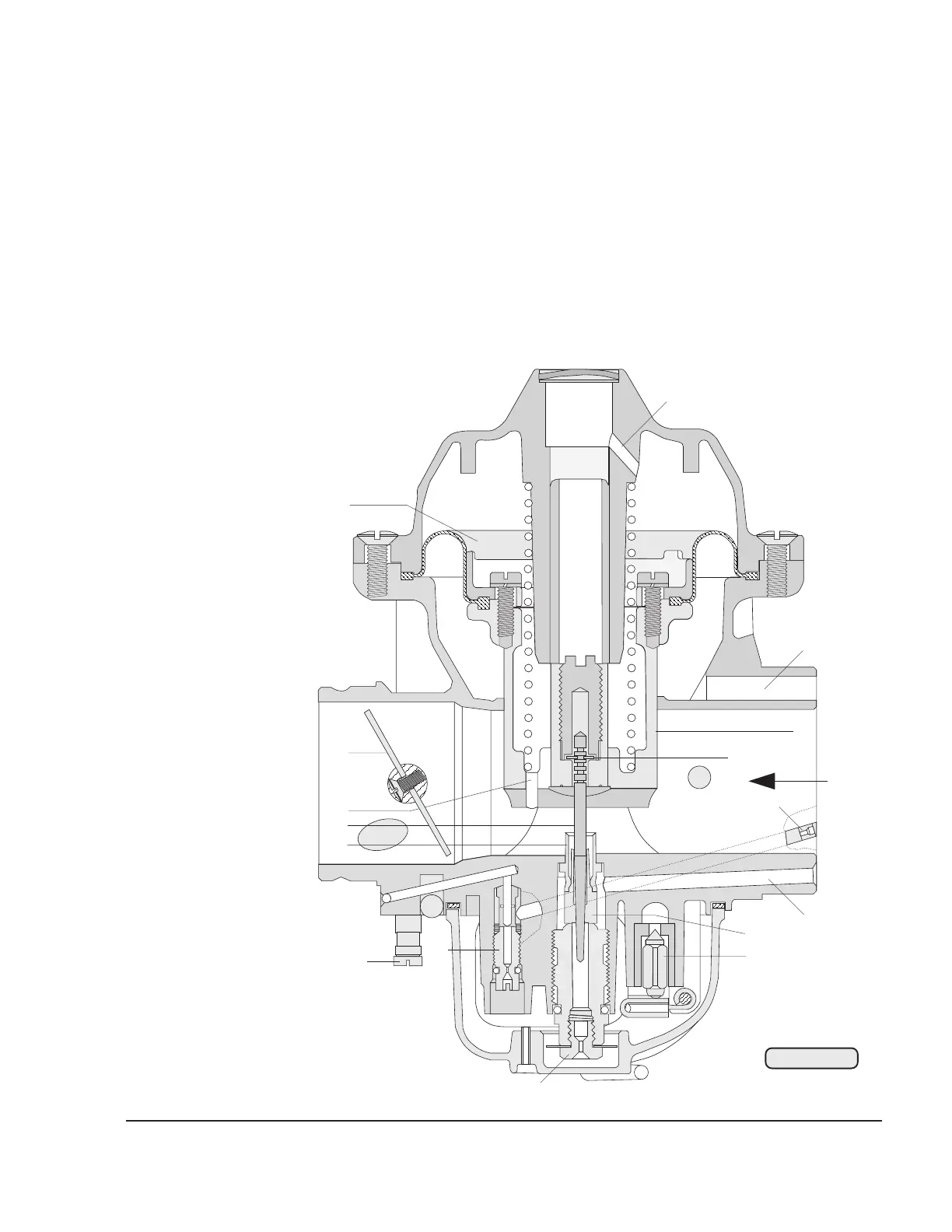
On its way from the float chamber to the venturi, the fuel passes through the
main jet (7), the mixing tube and the needle jet and in the diffuser tube (8) is pre-
mixed with air which is brought in from the air filter via the air duct (9) and the
atomizer in an annular flow around the needle jet. This air flow assists the
atomizing process and favors fuel distribution in the manifold.
The jet needle (10), which is responsible for part load, is kept in the defined
position by the retaining clip (11).
14
13
11
9
16
4
15
8
10
12
1
3
6
7
5
2
02931
Fig. 73-6

Table of Contents

Other manuals for Rotax 912 Series

Questions and Answers:

Question and Answer IconNeed help?

Do you have a question about the Rotax 912 Series and is the answer not in the manual?

Rotax 912 Series Specifications

General IconGeneral
Redline5800 rpm
TBO2000 hours
Displacement1211 cc
Bore79.5 mm
Stroke61 mm
Power Output80 hp (59.6 kW)
Compression Ratio9.0:1
Fuel TypeAvgas 100LL
Ignition SystemDual electronic ignition
Fuel SystemFuel Injected
Oil SystemDry sump
Engine Type4-cylinder, horizontally opposed, 4-stroke

Related product manuals