76-00-00
page 38
May 01/2007
Effectivity 914 Series
Edition 1 / Rev. 0
d02626
BRP-Rotax
Maintenance Manual
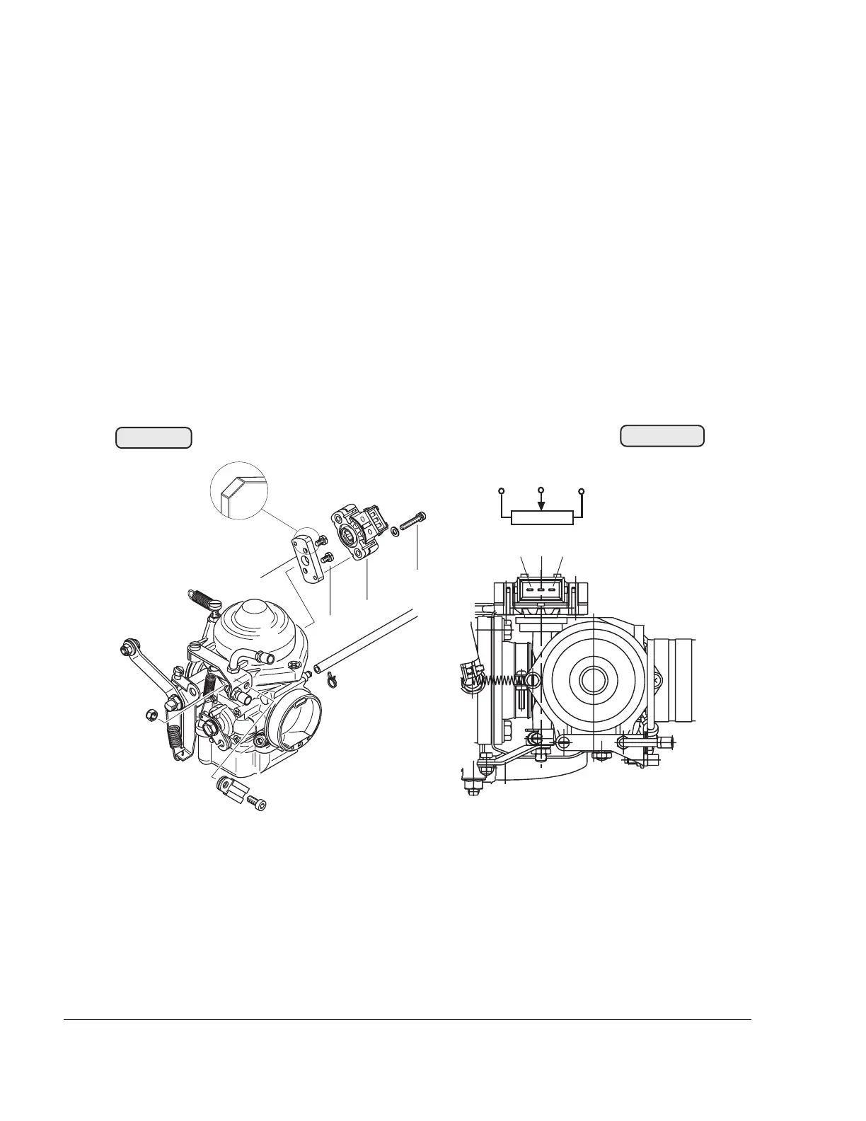
When reassembling the original throttle potentiometer, it is not
necessary to dismantle the adapter flange (2). This would
increase the installation tolerance unnecessarily.
When replacing the throttle potentiometer, pay attention to the
version used and if necessary, also remove the adapter
flange.
◆ NOTE: When assembling the adapter flange, ensure
that it is the appropriate model for the respec-
tive throttle potentiometer and that it is in-
stalled in the correct position (with the cut off
edge upwards). See Fig. 76-34
When installing the throttle potentiometer, check the version,
see Figs. 76-36 and 76-37 and ensure that it engages with free
movement in the flat surface of the throttle valve shaft. Secure
the allen screws M4x7 (3) and the combined screws M4x22 (4)
with LOCTITE 221. In addition, witness paint marking must be
applied to the screws.
00052
07717
Fig. 76-35
Fig. 76-34
(5) = minus
(6) = loop closed
(7) = positive
7
2
3
4
56
1
756
sloping edge

 Loading...


