78-00-00
page 18
May 01/2007
Effectivity 912/914 Series
Edition 1 / Rev. 0
d02627
BRP-Rotax
Maintenance Manual
After completion of installation as described, all the screw connec-
tions on the turbocharger bracket, exhaust manifold, exhaust bends
and the tension clamp must be tightened to the specified torques.
See Fig. 78-3
Tightening torque:
Allen screws (8) M10x50 turbocharger bracket 15 Nm/ 133 in.lb
Allen screws (27) M10x50 exhaust bracket 15 Nm/ 133 in.lb
hex. screw (6) M10 tension clamp 20 Nm / 177 in.lb
hex. nuts (1) M8 exhaust bend flange 12 Nm / 106 in.lb
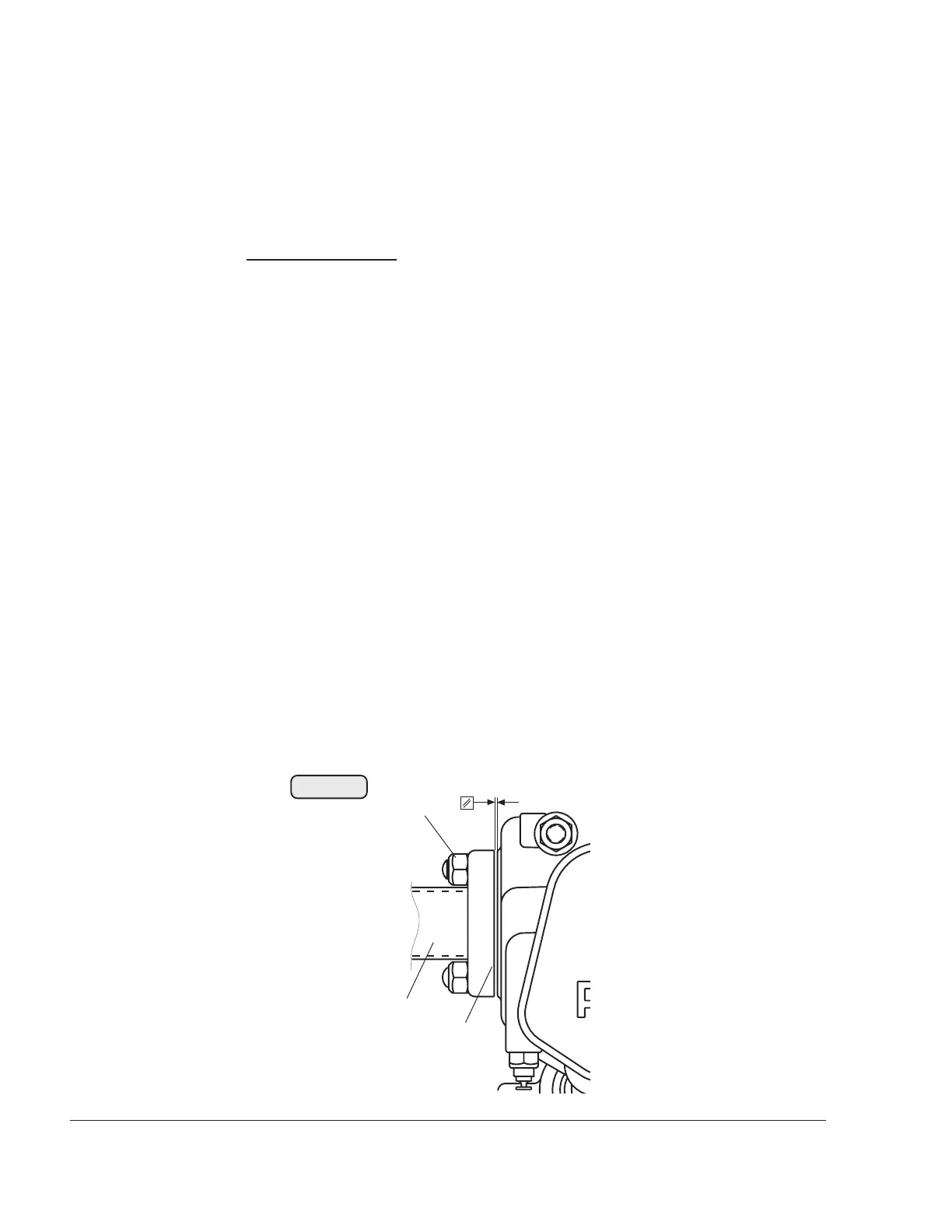
When tightening the exhaust bend flanges, ensure equal distance
between flange and cylinder head from top to bottom. The flanges (2)
of the exhaust bends (3) must not touch the cylinder heads. See Fig.
78-8
■ CAUTION: If the exhaust flange is deformed, it must be replaced.
After each disassembly, the lock nuts (1) must be
replaced with new lock nuts M8.
■ CAUTION: In the high temperature zone of the turbocharger and
exhaust system, use exclusively high grade, stainless
steel screws.
00165
Fig. 78-8
1
2
3

 Loading...


