BRP-Rotax
Maintenance Manual
72-00-00
page 56
May 01/2007
Effectivity 912/914 Series
Edition 1 / Rev. 0
d02622
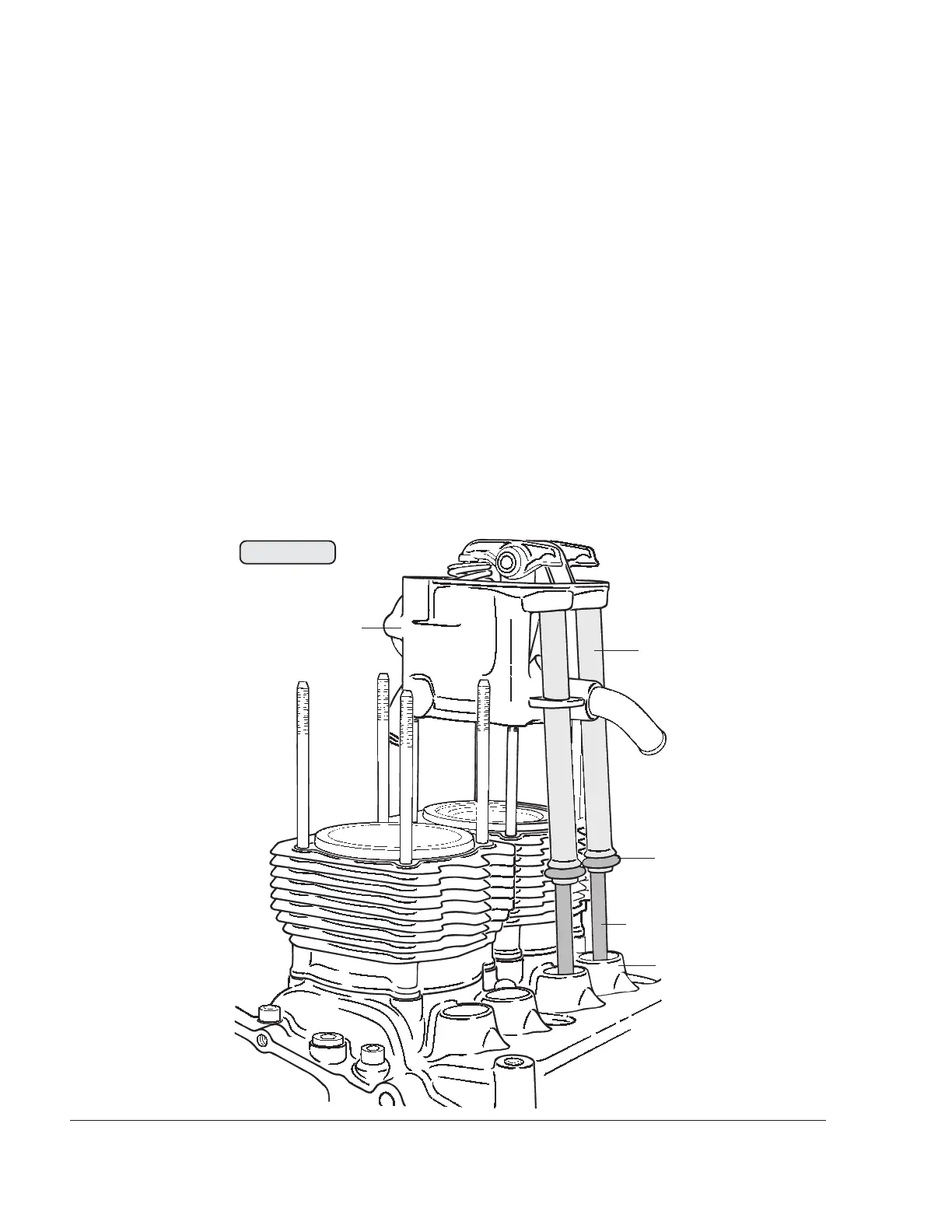
Keep both push rods (6) in position in the oil return tubes (7), seal oil bore of push
rods with finger and remove cylinder head (8). The oil return tubes remain with
the cylinder head. Remove O-rings (9) 16x15 from the oil return tubes or from
the crankcase (10).
Store cylinder head in such a way that the sealing surface and oil return tubes
are not damaged. Lift out oil filled push rods, stop oil from dripping by sealing
with finger. Coordinate push rods with cylinder heads to prevent any mix-up.
Mark the installation position of the push-rod with a suitable pen (e.g. touchup
pen) (e.g. ¨IV1“ for intake valve cylinder 1). If the parts are refitted in exactly the
same position and assignment as before, the push-rods can be used again. This
is because the parts have become broken in to each other in the course of
operation before disassembly.
00278
Fig. 72-58
6
7
8
9
10

 Loading...


