Effectivity 912/914 Series
Edition 1 / Rev. 0
74-00-00
page 13
May 01/2007
d02624
BRP-Rotax
Maintenance Manual
00397
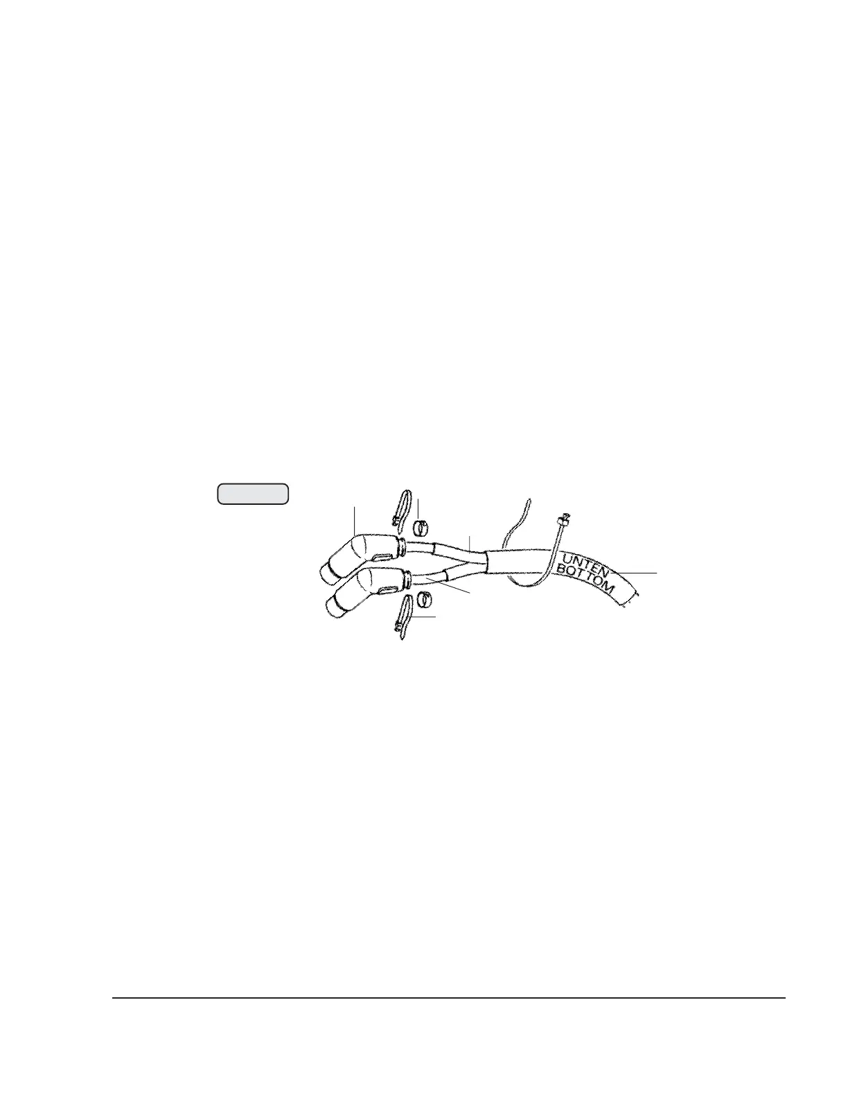
Fig. 74-7
6
1
2
3
4
5
- Check all cables and their plug connections for damage and correct
connection as per wiring diagram. See 74-00-00 sec. 3.13.
- Check all plug- and screwed connections for oxidation and tight fit.
- Check shorting cables and ignition switch. If ignition switch failure is
suspected, the shorting cable can be pulled off the ignition switch.
▲ WARNING: Proceed with particular care, because the ignition is not switched
off.
- Assure sufficient grounding between engine, battery and fuselage. Observe
the fuselage manufacturer's wiring diagram.

 Loading...


