BRP-Powertrain
Maintenance Manual
72-00-00
page 34
October 01/2010
Effectivity 912/914 Series
Edition 1 / Rev. 3
d04776
00257
13
14
15
11
12
8
9
10
16
7
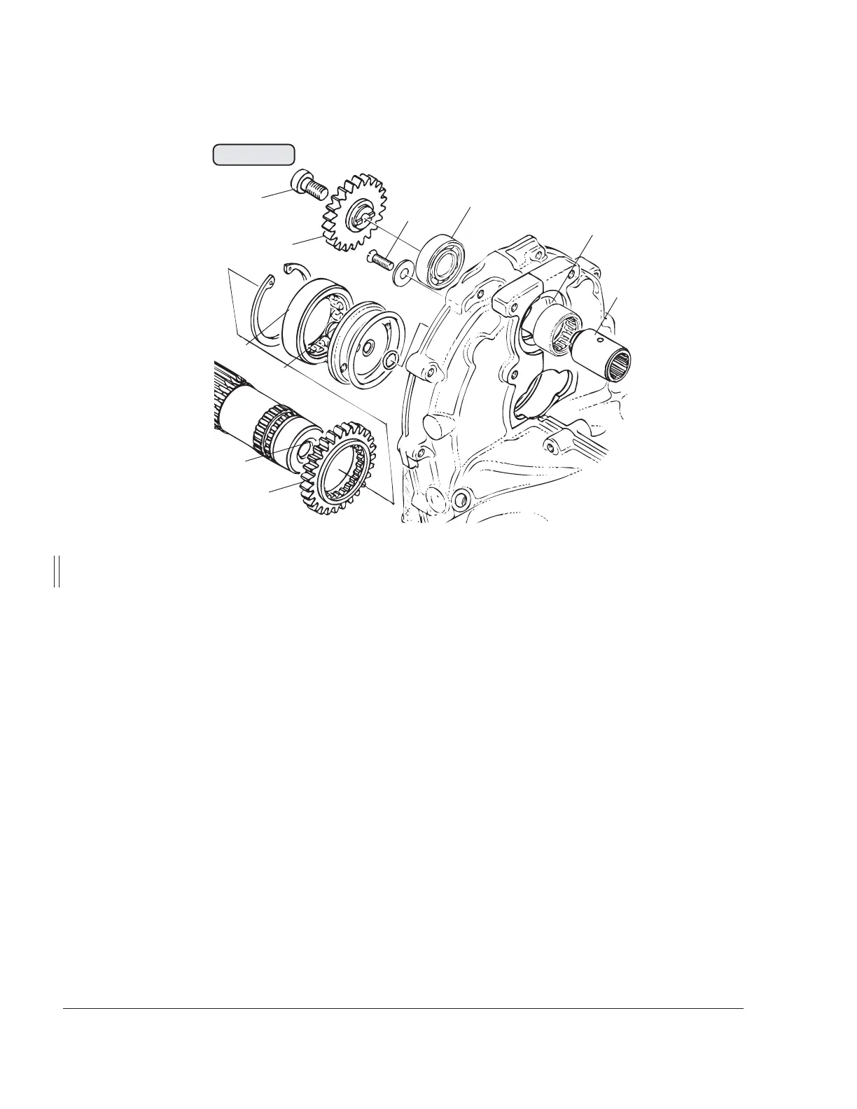
Fig. 72-32
Measure the inner diameter (13) of the propeller shaft and the bearing neck (14)
of the oil inlet flange (GB05 and GB06). Any wear will probably appear as a flat
area on the journal. Check the gear-tooth system of the drive gear (15) and the
vacuum pump gear (8). Carry out a visual inspection of the ball bearing (12) and
the cylindrical roller bearing (16).
■ CAUTION : The attachment screw (7) M8 of the vacuum pump gear for
hydraulic governor drive is 16 mm long (0.63 in.) and with a low
profile screw head. For vacuum pump drive, however, it is only
14 mm long (0.55 in.) with standard screw head.
Clean parts carefully and remove sealant residues. Check the sealing surface
and all oil bores in the governor flange (3) for free passage. Carry out a visual
inspection of the needle sleeve (11) and the gear-tooth system and bearing
surface of the drive sleeve (9). Ensure that the connecting face for the oil
pressure line is clean.
The governor must be sent to the manufacturer if any repair work becomes
necessary.
 Loading...