Effectivity 914 Series
Edition 1 / Rev. 3
79-00-00
page 21
October 01/2010
d04782
BRP-Powertrain
Maintenance Manual
00075
■ CAUTION: If the ball (4) installed under the pressure spring (5), the oil circuit
is interrupted and the turbocharger will be destroyed.
Insert pressure spring (5) and ball (4).
The pressure oil line (8) is attached with the banjo bolt (1) and sealing rings (2)
on both sides. Tightening torque 10 Nm (90 in.lb).
◆ NOTE: For recognition the banjo bolt is either marked with a blue color
or reads the label “OIL”.
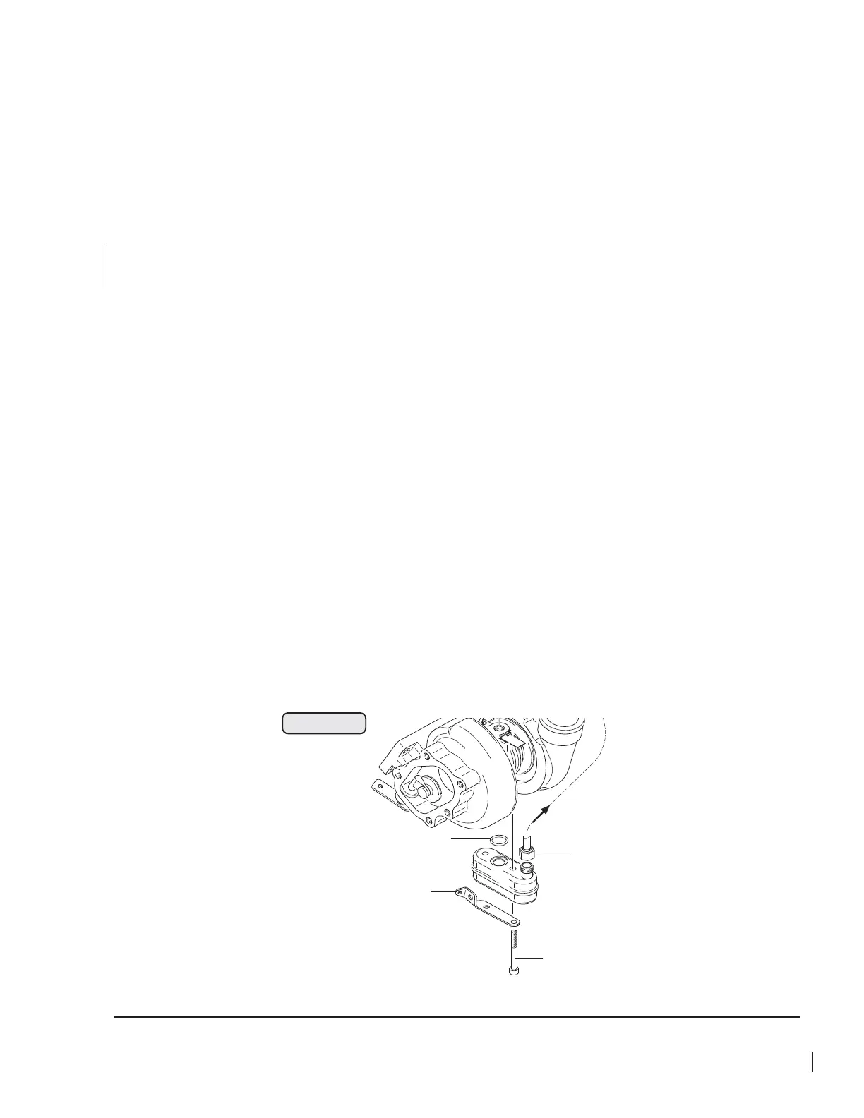
3.3) Oil sump (only on 914 Series)
See Fig. 79-15
◆ NOTE: The oil sump (1) is only removed in the event of damage or for
cleaning.
Remove tension spring from wastegate flap with a suitable tool.
Release collar nut (2) of the turbo oil suction line (3). Remove the 2 allen screws
(4) M6x55 and take off cable support (5), oil sump (1) and O-ring (6) 9x2.3.
Clean all components and check them visually. Also check thread and flange
surface of turbo charger housing. In the event of damage, replace oil sump.
Reassembly in reverse order.
The oil sump (1) is attached with the O-ring (6), cable support (5) and 2 allen
screws (4) M6x55.
Tighten collar nut (2) of the turbo oil suction line to 20 Nm (180 in.lb).
Secure the allen screws (4) with wire.
Fig. 79-15
6
1
2
3
4
5
 Loading...