Effectivity 912/914 Series
Edition 1 / Rev. 0
71-00-00
page 5
May 01/2007
d02621
BRP-Rotax
Maintenance Manual
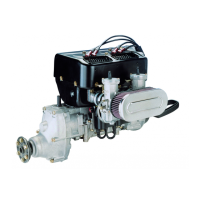
2.3) Engine components, engine views, cylinder designation and descrip-
tion of main axes
See Figs. 71-1 to 71-4 for engines of the 912 Series
See Figs. 71-5 to 71-9 for engines of the 914 Series
AS power take off side
MS magneto side
A points of attachment (for engine transport)
center of gravity
P zero reference point for all dimensions
◆ NOTE: Allow ±1 mm (0.04 in.) on all stated dimensions as manufactur-
ing tolerance
x,y,z axes for system of coordinates
Cyl. 1 cylinder 1 Cyl. 3 cylinder 3
Cyl. 2 cylinder 2 Cyl. 4 cylinder 4
 Loading...