76-00-00
page 34
May 01/2007
Effectivity 914 Series
Edition 1 / Rev. 0
d02626
BRP-Rotax
Maintenance Manual
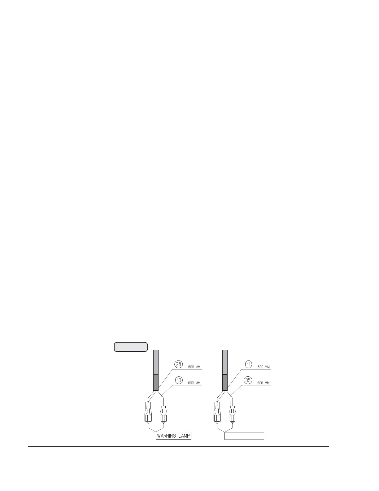
3.1.2.2) Caution lamps
See Fig. 76-30
The TCU is furnished with output terminals for an external red
boost lamp (WARNING LAMP) and an orange caution lamp.
Location of the lamps depends on type of aircraft and is limited
by the length of the wiring harness. Standard location is on the
instrument panel in the cockpit.
When switching on the voltage supply of the TCU, the function
of the two lamps is automatically tested. Both lamps light up
for 1 to 2 seconds and then go out. If this does not happen,
check the following:
- Inspection for physical damage.
- Check connections of wiring harness
- Check lamps for correct functioning
◆ NOTE: The two caution lamps are not included in the
delivery range of the engine.
■ CAUTION: In the event of physical damage or incorrect
operation, replace part without delay.
■ CAUTION: The negative poles (10, 11) must not be
attached directly to the battery potential. A
potentialfree 2-pin lamp socket must be used,
as the lamps are triggered via the negative
pole.
+12V
+12V
øV
øV
CAUTION LAMP
00211
Fig. 76-30
 Loading...