74-00-00
page 16
July 01/2008
Effectivity 912/914 Series
Edition 1 / Rev. 2
d04353
BRP-Rotax
Maintenance Manual
3.7) Generator coils
See Fig. 74-12.
If the generator does not work, the reason may be a defective or damaged yellow
alternator cable or a defective winding on the 8 alternator coils (3). Disconnect
alternator cables (yellow) and check resistance values.
Measure the resistance with a multimeter. See 74-00-00 sec. 3.12 and
74-00-00 sec. 5.
◆ NOTE: If the value measured corresponds with the values specified, the
cause may be a defective rectifier-regulator.
■ CAUTION : When performing any of the work described here, ensure that
no foreign objects can enter the ignition unit.
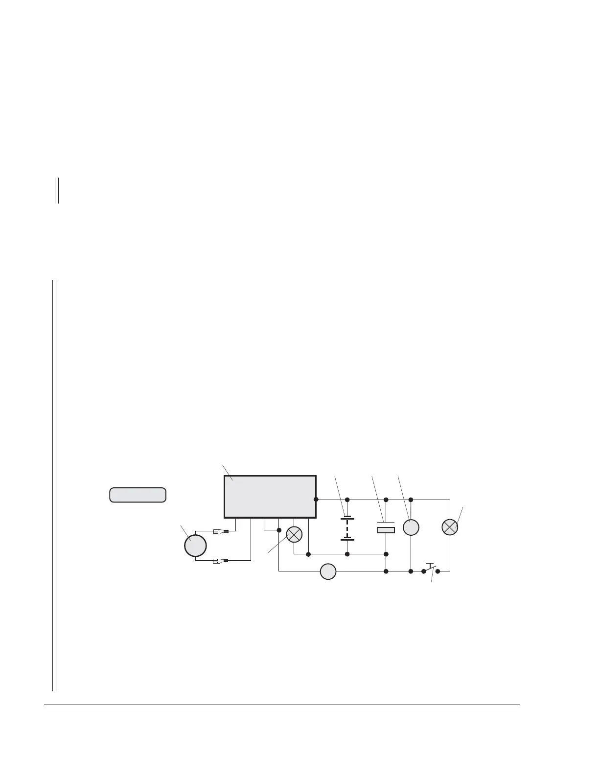
Checking the integrated alternator in operation:
The check of the internal alternator is carried out at idle speed and under load
on a 150 W (0.201 hp) consumer.
– Establish check circuit as shown on wiring diagram Fig. 74-12.
– Set engine speed to 4000 rpm.
– Check that charge indicating lamp goes out.
– Read off the idle voltage on the voltmeter (8) and record it in the 74-00-00
sec. 5 „Form sheets“.
– Close circuit-breaker (7), read off voltage under load on the voltmeter (8)
and record it in the 74-00-00 sec. 5 „Form sheets“ .
(1) Magneto-generator
(2) Recitfier regulator part no. 965345
(3) Charge indicating lamp 3W (0.004 hp)
(4) Battery 12 V charged
(5) Capacitor 22 000 µF/25 V
(6) Consumer (lamps) 150 W (0.201 hp)
(7) Circuit breaker
(8) Voltmeter
Testing is carried out at 4000 rpm with and without consumer.
GGR+BLC
G
3W
22 000
m
F
150W
+
-
V
A
12V 36Ah
2
1
3
4 5 8
6
7
Fig. 74-12
07539
 Loading...