Effectivity 912/914 Series
Edition 1 / Rev. 0
74-00-00
page 53
May 01/2007
d02624
BRP-Rotax
Maintenance Manual
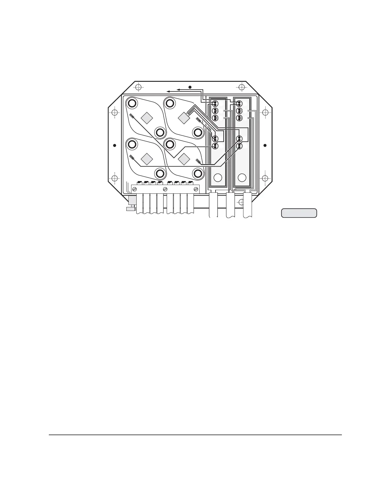
IGNITION CIRCUIT A
(1) alternator cable, red
shorting cable, white
(2) pick-up cable
white, for ignition circuit A-Cyl. 3
white/red, for ignition circuit A-Cyl. 4
(3) pick-up cable
white, for ignition circuit A-Cyl. 1
white/red, for ignition circuit A-Cyl. 2
(4) primary cable for ignition coil,
ignition circuit A, Cyl. 3/4, black (ground)
ignition circuit A, Cyl. 3/4, white
(5) primary cable for ignition coil,
ignition circuit A, Cyl. 1/2, black (ground)
ignition circuit A, Cyl. 1/2, white
04787
Fig. 74-35
Geberpaar
A1/2 B3/4
Geberpaar
A3/4 B1/2
3B
3T 1B
1T
2B
2T
4B
4T
B3/4
A1/2
Zündab-
schaltung:
Kondensator
oben:
Zündkreis A
Kondensator
unten:
Zündkreis B
B1/2
A3/4
6
9
10
1
4
5
B
A
zum
Kondensator
weiß - weiß/rot
weiß - weiß/rot
weiß - weiß/rot
weiß - weiß/rot
rot
rot
weiß
weiß
Generatorleitungen
Zündkreis A und B
3
7
8
Geberleitungen
von Zündkreis B
sind an beiden
Enden
rot
markiert
weiß
weiß
2
3B
3T
1T
1B
2B
2T
4B
4T
IGNITION CIRCUIT B
(6) alternator cable, red (from stator)
shorting cable, white (to capacitor)
(7) pick-up cable
white, for ignition circuit B-Cyl. 1
white/red, for ignition circuit B-Cyl. 2
(8) pick-up cable
white, for ignition circuit B-Cyl. 3
white/red, for ignition circuit B-Cyl. 4
(9) primary cable for ignition coil,
ignition circuit B, Cyl. 1/2, black (ground)
ignition circuit B, Cyl. 1/2, white
(10)primary cable for ignition coil,
ignition circuit B, Cyl. 3/4, black (ground)
ignition circuit B, Cyl. 3/4, white
3.21.2) Interference suppression box wiring diagram
 Loading...