74-00-00
page 4
May 01/2007
Effectivity 912/914 Series
Edition 1 / Rev. 0
d02624
BRP-Rotax
Maintenance Manual
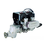
The standard equipment also includes an integrated AC generator (6) with an
external rectifier-regulator (12V DC 250 W).
For higher power requirements, it is possible to install an external alternator (12V
DC 600W).
◆ NOTE: A rectifier-regulator is already integrated in the external alterna-
tor.
The electric system comprises the internal generator with the charging coils
for the ignition and the ignition electrics with the electronic boxes and the 4
double ignition coils.
- Internal generator: See Fig. 74-2.
Consisting of stator with 8 generator coils (1) and the 2 independent ignition
charging coils (2) and the tenpole magneto ring (3)
The fly wheel hub (4) (ignition triggering) is attached to the magneto ring.
The 4 trigger coils (5) are fitted externally on the alternator.
- Ignition electrics: See Fig. 74-3.
Consists of 4 dual ignition coils (1) connected together by their magnetic
cores and two electronic modules (2) positioned above.
The 3-point suspension is with one each support on crankcase, ignition
housing and intake manifold.
For safety reasons, the ignition electrics must not be exposed to ambient
temperatures higher than 80 °C (176 °F).
 Loading...