Effectivity 914 Series
Edition 1 / Rev. 2
78-00-00
page 17
July 01/2008
d04356
BRP-Rotax
Maintenance Manual
Engine suspension frame / exhaust system assembly / exhaust bends
Screw the engine suspension frame (1) to the engine housing with the lock
washers and the allen screw M10x110 (3) and M10x35 (4). See Fig. 71-10 and
71-11 in 71-00-00.
Place distance sleeve (29) 10.5/17/15 into left arm of engine suspension frame
and attach exhaust bracket on engine housing (7) with washer, lock washer and
allen screw (27) M10x50.
Re-establish attachment (28) exhaust bracket engine suspension frame (not
supplied with engine). Tightening torque as specified by the fuselage manufac-
turer.
Place distance sleeve (10) 10.5/17/15 into right arm of engine suspension
frame.
Screw turbocharger assembly to the holder (26) on the engine housing,
complete with muffler and turbocharger bracket with washer, lock washer and
allen screw (8) M10x50 and allen screw M8x50 (25). The muffler is attached to
the exhaust bracket with the tension clamp (6) tightened to a torque of 15 Nm
(133 in.lb).
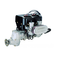
■ CAUTION: Position tension clamp so that the tension free zone (33) comes
to rest on the edge of the exhaust bracket. See Fig. 78-10.
00095
Fig. 78-10
6
33
 Loading...